Razor-thin, flat membrane potentiometers expand designers’ sensing repertoire.

Membrane potentiometers can solve many of the problems that conventional mechanical potentiometers cannot handle, especially those involving limited installation space, weight restrictions, and accuracy.
Conventional mechanical potentiometers are the old workhorse of electrical controls and position sensing. However, these conventional potentiometers can be heavy, bulky, and expensive compared to a newer type of device, the membrane potentiometer.
With some measuring only 0.5mm thick, ultra-flat membrane potentiometers are comparable to conventional potentiometers in terms of electrical parameters, but can be used in applications with limited installation space and at a lower cost.
Because most producers of membrane potentiometers offer customized products with only small tooling efforts, costs are very competitive, even for small prototype quantities. Three additional advantages are found in the basic construction of the membrane potentiometer; its ability to be fully sealed, the possibility of a hollow shaft design, and numerous wiper options, including operation by hand.
Design characteristics
In general, a membrane potentiometer is a voltage divider. It is constructed as an open circuit that only generates an output when the wiper connects the top and bottom circuits by applying pressure to the membrane surface. The spacing between the top and bottom circuit is constructed mainly of sealant adhesive, sealing it against external environmental factors, such as moisture or dust.
Most membrane potentiometers can be sealed up to an IP65 (NEMA4x) rating and beyond. Conventional potentiometers require a difficult assembly of the wiper, particularly in a “hollow shaft” assembly. Standard rotary potentiometers with a hole in the middle are hard and expensive to produce and are also hard to seal from environmental elements. The wiper inside must be “swimming,” which makes it difficult to seal and to achieve good linearity. With a membrane potentiometer, a hollow-shaft design is much simpler, more reliable, and more cost effective.
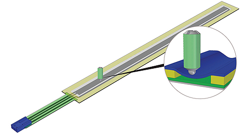
The wiper covers about 10 to 50% of the active width on the membrane potentiometer. Typical wiper materials can be steel, brass, or a variety of hard plastics.
The wiper for the membrane potentiometer can be as simple as a small plastic knob sliding across the surface, requiring no external electrical contact. Most membrane potentiometers can also be operated by sliding a finger over the surface or even with a contactless magnetic design.
The spacing adhesive requires a minimum width of 2 to 3mm on all sides of the membrane potentiometer. The ideal width of the resistive active area should be between 3 and 6mm, but can also be extended to 10 or 12mm. Linear elements can reach up to 760mm in active length, while rotary elements with a central hole can measure from 20 to 450mm in diameter.
The life cycle and operating temperature correspond to those of mechanical potentiometers. Depending on the design, however, even up to 100 million operations are possible. The operating temperature can range from 40°C to 85°C (104°F to 185°F), with some models achieving a maximum temperature of 125°C (257°F). The design of membrane potentiometers makes temperature compensation unnecessary if being operated in a voltage divider mode. Electromagnetic interference will also not affect the system.
Installation process and wiper design
The flat design of membrane potentiometers means they can be brought close to the motion area of the device it is measuring without requiring a lot of installation space. They adhere to a substrate by removing the protective paper and applying it to the surface, with other options including snap-in mounting or the use of screws.
With small quantities, off-the- shelf wipers might be the easiest choice, whereas with higher quantities or in cases where space is limited, a custom designed wiper might make more sense. One application might require a spring-loaded screw, while another will require a spring-plate attached to a piece of POM/Delrin plastic. Each application is specific to the requirements of installation space, cost and accuracy.

A typical membrane potentiometer is only a razor-thin 0.5mm thick and can have a width from 8 to 12mm and lengths up to 760mm.
If lifecycle requirements are high, a magnetic wiper is recommended for contactless connection. For most applications, however, a spherical wiper will do. The typical wiper covers about 10 to 50% of the active width. Materials such as steel, brass and hard plastics (e.g. Delron, Delrin) are typical, but depend on the type of membrane potentiometer. The specific manufacturer should be able to offer advice regarding the right choice of material.
Different surface pressures are defined depending on the application, but in general, a range of 1 to 6 Newtons (N) is recommended for most applications, depending on whether the membrane potentiometer is configured in a standard foil layout or in a hybrid version with additional metal bonds to strengthen the structure. A standard off-the-shelf wiper is usually divided between a 1 to 3N and a 3 to 6N range.
Electrical characteristics
The electrical characteristics will vary somewhat with the design, but are generally the same as standard mechanical potentiometers. That is, they have a similar output to that of a conventional potentiometer acting as a voltage divider. So for instance, if there is 5V across a potentiometer and the position of the wiper is in the middle, the output signal would be 2.5V. As the wiper moves up and down, the voltage will change. This analog signal can then indicate the position of the wiper.
When compared to a conventional precision potentiometer, the most significant difference is the method of achieving linearity, which is the difference between the theoretical or calculated output voltage and the actual output voltage. Hence, the typical linearity offered is 2% for standard linear potentiometers, although FR4-based membrane potentiometers can reach as little as 0.5%.
While the conventional potentiometer may use laser-trimming to achieve linearity, membrane potentiometers, which are based on a PET material, rely on production improvements to improve linearity. The most important production improvement is improving the uniformity of the resistive ink, making sure that printing the resistive ink is uniform throughout. This can be done by adjusting the mesh size of the silk screen depending on the viscosity of the resistive ink.
More significant than linearity are repeatability and hysteresis. The accuracy of membrane potentiometers can be as good as 0.01mm over a length of 500mm, but most standard membrane potentiometers range anywhere from 0.05mm to 0.1mm. The main impact on all of the electrical outputs is found in the mechanical motion and stability of the wiper. As a benchmark, energy dissipation of up to 1W and a dielectric strength of 500V are standard, with isolation strength of 100VDC also possible.
Applications
Many position sensing applications can be solved using membrane potentiometers. An improved design, creating linear output signals right next to the motion device, can sometimes increase accuracy over a conventional rotary potentiometer, which is connected by gears far from the actual motion being measured. While conventional mechanical potentiometers are cost intense, membrane potentiometers can reduce costs significantly.
A typical application, due to the small height of membrane potentiometers, is the linear measuring of actuators. Control valves are another application, in which currently the standard requires gears and a turning sensor to measure position. The structure required to install and use a membrane potentiometer is simpler than those used in the large and difficult mounting of certain conventional potentiometers.
In many applications, both rotary and linear membrane potentiometers can be used in the same device. For instance, a seat level adjustment requires linear motion, while inclining the seatback angle requires rotary motion. Similar applications are found in automotive interiors, where sliding doors, sun roofs, and other needs require small installation spaces and low weight.
Another simple solution to space problems is to use the PCB (printed circuit board), which already exists in many applications, as a base for the membrane potentiometer. The printed circuit board can be filled, and afterwards, the membrane potentiometer can be adhered to the board and the connectors inserted directly into the PCB.
Other applications, which use a membrane potentiometer mainly for cost saving reasons, are string-pots or wire sensors and magnetic tape. Additionally, membrane potentiometers can be fully integrated into a keypad for hand-control. An integrated potentiometer can avoid installation holes, as needed by a standard potentiometer, and can create a completely sealed and washable front panel surface.
Discuss this on The Engineering Exchange:

Hoffmann + Krippner, Inc.
www.hoffmann-krippner.com
Filed Under: Potentiometers, SENSORS, TEST & MEASUREMENT, Motion control • motor controls

Tell Us What You Think!