Design World

  • Home
  • Technologies
    • 3D CAD
    • Electronics • electrical
    • Fastening & Joining
    • Factory automation
    • Linear Motion
    • Motion Control
    • Test & Measurement
    • Sensors
    • Fluid power
  • Learn
    • Ebooks / Tech Tips
    • Engineering Week
    • Future of Design Engineering
    • MC² Motion Control Classrooms
    • Podcasts
    • Videos
    • Webinars
  • LEAP AWARDS
  • Leadership
    • 2022 Voting
    • 2021 Winners
  • Design Guide Library
  • Resources
    • 3D Cad Models
      • PARTsolutions
      • TraceParts
    • Digital Issues
      • Design World
      • EE World
    • Women in Engineering
  • Supplier Listings

NASA’s Lunar Orbiter Spots Beresheet’s Crash Site

By Jennifer DeLaOsa | May 17, 2019

Share

NASA’s Lunar Reconnaissance Orbiter (LRO) has spotted the crash site of the Beresheet lander, which confirms its unfortunate demise.

The first privately funded mission to the moon launched February 21 with Israeli non-profit SpaceIL’s Beresheet spacecraft. Thursday, April 11, was the day Beresheet made its descent toward the moon’s surface, broadcasted for all to see during a live stream.

Everything seemed fine up until Beresheet’s final moments, when it ultimately crashed on the surface of the moon.

The left side of the image below depicts the lander’s crash site at 32.5956°N by 19.3496°E at an elevation of about 2,613 m (1.6 mi). The right depicts the same area with the brightness changed to enhance the surface changes.

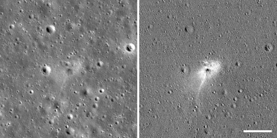
(Image Source: NASA/GSFC/Arizona State University)

According to an article by Arizona State University’s Lunar Reconnaissance Orbiter Camera (LROC), the spacecraft hit the moon’s surface 1,000 m/s (about 2,237 mph) faster than planned. LROC explains, “The mishap occurred late in the descent profile when the main engine failed—resulting in a very low-angle (<10°), high-speed impact.”

LROC took the photo April 22, 2019, which was 11 days after the impact.

The dark center of the impact is said to be about 10 m (33 ft) across, and is darker than the surrounding area by 10 percent. Currently, a crater isn’t detected, but there could be a number of reasons for this including its small size, the low angle of impact, and the spacecraft’s fragility, among others.

The region circling the darkened impact point, which spans 30 to 50 m (98 to 164 ft) and includes a jettisoned part that extends 100 m (328 ft) southward, is 20 percent brighter than normal. The increased reflectance “was likely caused by gases or very fine high-speed particles rapidly moving away from the impact site, which smoothed the upper layer of regolith and redistributed fine soil particles, which in turn increased reflectance,” according to LROC.

The gif below provides further confirmation, comparing a December 16, 2016 photo of the area with the April 22, 2019 image.

As of right now, investigations are ongoing to figure out exactly what went wrong. However, early reports surfaced that human error may have been the culprit. A command sent by the team may have started a fatal chain reaction that sparked the main engine to fail.

SpaceIL has already announced that the Beresheet 2 mission is currently in the works.


Filed Under: Aerospace + defense


Related Articles Read More >

Ontic acquires Servotek and Westcon product lines from Marsh Bellofram
Flexible rotary shafts support thrust reverser on 150 LEAP 1-A turbofan engines
Drone-mounted inspection breaks barriers for F-35
TriStar, a misunderstood failure of design

DESIGN GUIDE LIBRARY

“motion

Enews Sign Up

Motion Control Classroom

Design World Digital Edition

cover

Browse the most current issue of Design World and back issues in an easy to use high quality format. Clip, share and download with the leading design engineering magazine today.

EDABoard the Forum for Electronics

Top global problem solving EE forum covering Microcontrollers, DSP, Networking, Analog and Digital Design, RF, Power Electronics, PCB Routing and much more

EDABoard: Forum for electronics

Sponsored Content

  • Global supply needs drive increased manufacturing footprint development
  • How to Increase Rotational Capacity for a Retaining Ring
  • Cordis high resolution electronic proportional pressure controls
  • WAGO’s custom designed interface wiring system making industrial applications easier
  • 10 Reasons to Specify Valve Manifolds
  • Case study: How a 3D-printed tool saved thousands of hours and dollars

Design World Podcasts

May 17, 2022
Another view on additive and the aerospace industry
See More >
Engineering Exchange

The Engineering Exchange is a global educational networking community for engineers.

Connect, share, and learn today »

Design World
  • Advertising
  • About us
  • Contact
  • Manage your Design World Subscription
  • Subscribe
  • Design World Digital Network
  • Engineering White Papers
  • LEAP AWARDS

Copyright © 2022 WTWH Media LLC. All Rights Reserved. The material on this site may not be reproduced, distributed, transmitted, cached or otherwise used, except with the prior written permission of WTWH Media
Privacy Policy | Advertising | About Us

Search Design World

  • Home
  • Technologies
    • 3D CAD
    • Electronics • electrical
    • Fastening & Joining
    • Factory automation
    • Linear Motion
    • Motion Control
    • Test & Measurement
    • Sensors
    • Fluid power
  • Learn
    • Ebooks / Tech Tips
    • Engineering Week
    • Future of Design Engineering
    • MC² Motion Control Classrooms
    • Podcasts
    • Videos
    • Webinars
  • LEAP AWARDS
  • Leadership
    • 2022 Voting
    • 2021 Winners
  • Design Guide Library
  • Resources
    • 3D Cad Models
      • PARTsolutions
      • TraceParts
    • Digital Issues
      • Design World
      • EE World
    • Women in Engineering
  • Supplier Listings