Do you need a network for motion control? Your choice will depend on your requirements for jitter free motion. Here’s a brief synopsis of the more popular fieldbus networks.
Multi-axis motion control typically uses event-based synchronization. Thislevel of synchronization is defined as scheduled, absolute hard delivery of time-critical cyclic data across the network. Delivery variability must be less than 1 µs, which is also known as jitter.
While a number of networks exist for “motion control,” it is important to define your time delivery needs for the given application. Synchronized multi-axis motion will have different timing needs than a divert actuator on a conveyor system.
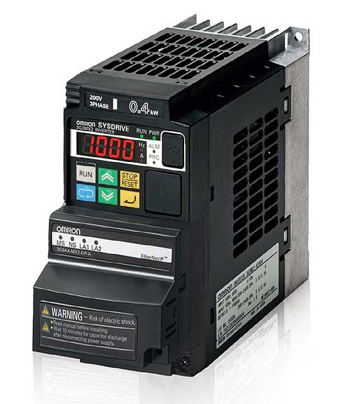
Compact Omron 3G3MX2 AC Drives include front panel mounting 3G3AX-MX2-EIP-A EtherNet/IP communication interface unit that imparts network slave capabilities to the ac drives. The EtherNet/IP interface makes it easy to standardize on 3G3MX2 ac drives.
Omron Industrial Automation
www.Omron247.com
A requirement for jitter free motion narrows your network choices. Here is a brief synopsis of several popular fieldbus networks and whether they suit jitter free motion control.
EtherCAT®
Ethernet for Control Automation Technology (EtherCAT) was developed by the Beckhoff company. It is fast and deterministic, and processes data using dedicated hardware and software such as Beckhoff’s TwinCAT operating system and TwinCAT Y driver.
It uses a full duplex, master-slave configuration, and accommodates any topology. It can process 1000 I/O points in 30 µs and communicate with 100 servo axes in 100 µs. Axes receive set values and control data, and report actual position and status. A distributed clock technique that is a simple version of IEEE 1588 synchronizes the axes with less than 1 µs of jitter.

The MC464 Motion Coordinator motion and machine controller includes an EtherCAT Master drive interface module. The new module provides tight synchronized control for up to 64 slave axes. Up to seven modules may be added, each providing eight 100 nanosecond registration inputs which can be mapped to any axis.
Trio Motion Technology
www.triomotion.com
The master initiates all communications, which controls traffic and guarantees determinism. Slaves range from intelligent nodes to 2-bit I/O modules. The physical media can be either 100Base-TX fiber optic cable or E-bus.
EtherCAT transmissions often involve very short distances, for example between two EtherCAT terminals within the same terminal block, so an additional physical layer was developed–the E-bus. The E-bus is based on Low Voltage Differential Signal transmission (LVDS), from the IEEE standard P1596.3-1995.
This protocol can deliver fast throughput because messages are processed in hardware before they are forwarded to the next slave. Slaves read data relevant to them as the data frame passes and they insert new data into that same data stream on the fly. This procedure does not depend on the run-time of the protocol stack, so processing delays are typically just a few nanoseconds.
EtherCAT can be configured to interoperate with other TCP/IP networks, including Ethernet versions. It can work with UDP in a protocol stack, however it won’t be deterministic. Also, switches and routers between the master and the slaves will negate determinism. Lastly, this protocol is compatible with Sercos.
EtherNet/IP (EIP)
Standard Ethernet cannot guarantee jitter of less than 1 µs because of the data layer’s use of Carrier Sense Multiple Access/Collision Detection (CSMA/CD) techniques to control packet transmission. To over come this issue, ODVA developed EtherNet/IP, and it did so without changing any of the lower layers of Ethernet.
Many people assume that the IP in EtherNet/IP indicates that this network uses part of the Internet Protocol. It does not. The IP stands for “Industrial Protocol,” a reference to the use of the Common Industrial Protocol (CIP™) standards within its layers. EtherNet/IP is an industrial protocol for the application layer of the OSI model.
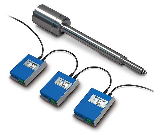
The ACS with Ethernet supports Ethernet/IP, allowing easy connectivity to Allen Bradley and other PLCs and HMIs. With built-in configurations for all of Tolomatic’s electric actuators, the ACS makes creating linear motion simple.
Tolomatic
www.tolomatic.com
Because of its reliance on CIP Motion, EtherNet/IP puts timing information into the end devices to handle the real-time control needs of an application. Thus, this network can deliver sufficient deterministic control for closed loop drive operation using standard, unmodified Ethernet. CIP is also used by DeviceNet and ControlNet, so these networks are interoperable.
CIP Motion uses application protocols to set position, speed, and torque within a drive. It uses the IEEE-1588 compliant Precision Clock Synchronization (CIP Sync technology) standard.
CIP Sync consists of a Time Sync object and services to synchronize nodes to within ±100 ns of one another. The clocks in the end devices are tightly synchronized and information in the message is time-stamped. Some time delay can be occur in the receipt of a message by a device. This jitter comes from the fact that the message must travel through the TCP/UDP/IP stack, where the amount of overhead can affect the timing. The use of UDP puts a burden on the designer to ensure that packets go to the right nodes. You can confine nodes needing guaranteed transmission to one segment of an EtherNet/IP network. Usually, this jitter is too small to affect the motion axes. This protocol allows 100 axes to be coordinated with a 1 ms network update to all axes.
Ethernet Powerlink
Ethernet Powerlink is a software-only protocol supported by the Open Modular Architecture Controls (OMAC) Users Group. It uses cyclic communication with time-slot division to deliver cycle times of 200 µs with 1 µs jitter. This network guarantees determinism.
It follows a master/slave model, so real-time domains handle time critical data and non real-time domains handle non time-critical data. In the protocol’s terminology, time critical data are sent in the “isochronous phase” of the schedule and non time-critical data are sent in the “asynchronous phase.” A Managing Node governs access to the physical medium ensuring that only one node has access to the network at a time.
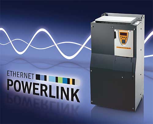
The ACOPOSinverter P84, from B&R, includes an integrated POW ERLINK interface. Its performance range is from 0.37 to 500 kW. An encoder interface can be added to the inverter for applications with strict requirements for speed or torque control. This allows movements to be synchronized with the servo drives.
www.br-automation.com
All networked nodes synchronize to the Managing Node’s clock at start-up. The Managing Node assigns a fixed time window for each node to transfer time-critical data. Any node can listen to all data during this isochronous phase.
The precision of this basic cycle time is what guarantees real-time data transmission. Individual phase lengths can vary as long as the total of all phases does not exceed the basic cycle time boundary monitored by the Managing Node. You can configure the duration of the isochronous and the asynchronous phases.
Like several of the other motion networks, this protocol uses IEEE 1588 to synchronize traffic across multiple real-time segments. You can set some nodes to share common time slots while they are transferring isochronous data during a basic cycle. The use of repeating hubs rather than switching hubs will help ensure determinism.
A key feature of Ethernet Powerlink is its ability to isolate the machine and the factory network, which helps keep data secure.
DeviceNet
DeviceNet is an open multi-drop network that connects and communicates data between industrial controllers and I/O devices. It can transport cyclic data and non-cyclic data.
It is an industrial protocol managed by the Open DeviceNet Vendors Association (ODVA). Unlike Ethernet/IP, which is based on the Ethernet physical layer, DeviceNet is based on the CAN (Controller Area Network) protocol. It uses CAN for its data link layer (layer 2). It too uses Common Industrial Protocol (CIP™) for the application layer (layer 7 in the OSI network model). CIP lets DeviceNet integrate with controls, multiple CIP networks such as EtherNet/IP and ControlNet, and other Internet technologies.
The CAN protocol’s minimum overhead requirement means that DeviceNet can deliver messages within a time frame of 10 msec, depending on cable length, data packet size, and so on.
Even though it is viewed as a producer-consumer network, it is usually set up in either a master/slave arrangement or as peer-to-peer. It will support multiple masters on one logical network. The maximum of devices on one logical network is 64 devices. It uses a trunk-line topology with separate buses for signal and power. Thus, it can power some devices connected to it, such as small sensors and switches. It supports 3 baud rates depending on the cable chosen: 125 kbit/s, 250 kbit/s, and 500 kbit/s. The length of the truck has an inverse relationship to transmission speed. Data packets are from 0 to 8 bytes.
PROFINET
PROFINET has been described as an “all-encompassing Industrial Ethernet” because it supports discrete control, process automation, motion control, peer-to-peer integration, vertical integration with enterprise IT systems, functional safety, energy management, fast IO, and more.
It uses standard IEEE 802.3 Ethernet and IEEE 802.11 wireless Ethernet. Wireless is a necessity to control untethered devices like Automatic Guided Vehicles.
This protocol is often selected for applications that use a number of Siemens’ products. It is based on RPC (Remote Procedure Call) and DCOM (Distributed Component Object Model) technologies, but uses traditional Ethernet software and hardware to organize accessing, configuring, and controlling tasks.
Profinet is not Profibus running over Ethernet. Profibus uses a data-focused approach to move I/O from device to device at 12 MB. Profinet, on the other hand, lets you locate and exchange data on cyclic schedules or trigger events, and has transmission rates that range from 10 to 100 MB.

Optical Link Modules (OLM P22 and OLM G22) for Profibus networks use bayonet fiber optic connector (BFOC) technology and two electrical interfaces of the sub-D type. This enables two separate electronic Profibus segments to be integrated into one optical network structure, such as a redundant ring. The transmission rate of a fiber-optic link of up to three kilometers in length is up to 12 Megabaud/second and does not depend on the distance.
Siemens Industry Automation Division
www.siemens.de/profibus
The protocol divides a communication cycle into standard TCP/IP open channel and a deterministic real-time channel. The division ratio is system dependent and chosen by the designer. It prioritizes the data messages in the switches using IEEE 1588 priority tagging, thus, it offers response times of 5 to 10 ms. Cycle time is 1 ms, jitter accuracy is 1 µs, and determinism is guaranteed.
The Component Object Model (COM) interface has two parts. The implementation part refers to the structure of the object and is only available to developers. The interface part consists of access methods supported by the object, and is available to the world.
All Profinet devices must obtain certification from the Certification Office of the PROFIBUS User Organization to ensure interoperability and compatibility. Certification involves three steps: test the Profinet Object Model, test the XML file provided by the developer for interoperability, and link the device to a network of other Profinet devices to verify how well the device operates on a loaded network.
Enhancements to this network include ProfiSafe, which incorporates safety protocols for the manufacturing and processing industries.
Sercos
Sercos is a digital bus that interconnects motion controls, drives, I/Os, sensors and actuators for numerically controlled machines and systems. It supports serial communication of standard closed-loop real-time data over a noise-immune, fiber optic ring (Sercos I & II) or Industrial Ethernet cable (Sercos III).
With this protocol, all servo loops are normally closed in the drive to reduce the computational load on the motion controller, synchronize a greater number of motion axes than it otherwise could, and reduce the effects of transmission delay between the motion control and drive.
Initially developed for use with CNCs, Sercos has evolved to become a universal real-time communication interface for all types of automation applications. More than 500 standard parameters are specified to define the interaction of controls, I/Os, and peripheral devices in many applications.
You can designate one drive to handle multiple devices, such as I/Os and sensors, permanent magnet servomotors, high horsepower induction servomotors, and linear motors with the configuration set-up parametrically. You can also configure multi-vendor control systems with plug and play interoperability.
Sercos III is the open, IEC-standard third-generation version that transmits data over Industrial Ethernet. It combines the best of both Ethernet and previous Sercos designs for deterministic bi-directional real time motion and I/O control. A key feature is that it overcomes the wasted bandwidth in TCP/IP-based Ethernet bus implementations because it uses Ethernet frames–defining a new, registered EtherType for Sercos. In addition, it delivers rich I/O communication while enabling conventional protocols (TCP/IP, UDP and others) to be transmitted over the same Ethernet network efficiently in parallel with Sercos real-time communication.
With Sercos III, you can achieve cycle times as low as 31.25 microseconds. This protocol supports line or ring topologies and up to 511 slave devices on one network. Multiple networks are possible.
It also supports safety functions up to SIL3 according to IEC 61508 through the CIP Safety for Sercos.
Wireless networking
For discrete motion control applications, wireless networks require considerable design to implement. In many cases, you have better options through wired networks.
The success of wireless technologies in consumer electronics gives rise to the idea that these technologies could work well in industrial applications. The potential to save on wiring and installation costs is especially attractive. However, wireless technologies, without modification, are unlikely to meet the stringent reliability and timing requirements of industrial applications—particularly motion control. Adding wireless to an environment of wired networks can increase the difficulty of meeting reliability and timing requirements due to the properties of the radio channels. Wireless networks such as Bluetooth and IEEE 802.15.4 support data rates of hundreds of kbit/s to a few Mbit/s. Plus, the range of these wireless networks may be an issue, depending on the application.
The channels of wireless networks in a discrete motion application are prone to transmission errors caused by channel outages that occur when the received signal strength drops below a critical threshold and interference. Transmission errors, which often result in dropped packets, are usually unacceptable even in a wired fieldbus network.
Path loss is another problem with wireless systems. Radio signal strength decreases with the distance between a transmitter and a receiver. Changes to correct this issue can be more expensive than installing a wired network.
Another issue is that wireless transceivers operate as half-duplex. They cannot transmit and receive simultaneously on the same channel. The problem here is an increase in packet transmission time.
Then, noise and distortion are issues in discrete industrial applications. Even motors will cause enough noise to interrupt wireless signals.
Discuss this on The Engineering Exchange:
EtherCAT Technology Group
www.ethercat.org
EtherNet Powerlink
www.ethernet-powerlink.org
ODVA
www.ODVA.org
Profibus-Profinet International
www.profibus.com
Sercos North America
www.sercos.com
::Design World::
Filed Under: Factory automation, CONNECTIVITY • fieldbuses • networks, Drives (ac) + VFDs + starters, Wireless • 5G and more, Wireless devices, Motion control • motor controls


Tell Us What You Think!