by Chris Francis
When designing low noise circuits – signal conditioning circuits, amplifiers or analog to digital converter interfaces, for example – SPICE simulation can be helpful in ensuring you have a low noise solution, particularly where signal conditioning circuits are high gain.
Input referred or output noise?
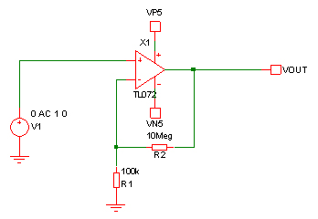
One decision you need to make in noise analysis is whether to look at input referred noise or output noise. While devices are often specified with the noise “input referred”, this is partly because, with an opamp for example, the output noise will depend on gain so is not constant. So, if you have 1nV/√Hz on the input of an opamp, the output noise might be 10nV/√Hz if you have a gain of 10 and 100nV/√Hz if you have a gain of 100. So, quoting the noise “input referred” makes sense in that case. However in most cases you are really interested in the noise out of your circuit. Also, input referred noise is calculated by taking the output noise and applying the inverse of the circuit transfer function to come up with the input referred value. This can give confusing results if the circuit has significant filtering, particularly if it is accompanied by a device with noise which increases while the circuit gain is reducing. Even with a simple low-pass roll-off the results can be confusing. For example, take this simple circuit:

If you analyse the output noise you get this:
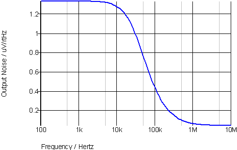
Which makes sense because the circuit naturally has around 35kHz 3dB point due to the limited bandwidth of the opamp. However, if you look at the input referred noise you get a totally different picture:

This is because of the mathematical transformation of the output noise through the inverse of the amplifier transfer function. The amplifier transfer function is a simple low pass with a second pole at a few MHz so input referring the output noise results in the apparent rise at high frequencies. Bear in mind this is not a rise in the output noise – it is a rise in the input referred noise and so is not really relevant. So it is usually best to use output noise to avoid any confusion.
AC analysis compared to noise analysis
While a noise analysis and AC analysis have very similar setups (start frequency, end frequency etc) they are totally separate analyses and do not need to be run together. The noise analysis requires the definition of the output node and, if you are wanting an input referred noise result, and input source. It is always useful to run an AC analysis at the same time as a noise analysis so that if you make an adjustment which stops the circuit working you will notice it. Otherwise you might just think you have designed a very low noise circuit but in reality it is not an amplifier any more.
Setting start and stop limits
For a noise analysis you need to decide what frequencies to analyse. If you are amplifying signals up to 10kHz then you might decide to limit your analysis to 10kHz but that could give an unrealistically low noise level if the circuit you are then feeding your signal to has a wider bandwidth. If the next amplification stage has a 1MHz bandwidth then it would be more realistic to use that. If you are supplying the signal to a 1Ms/s analog to digital converter (ADC) then you would also need to use a frequency higher than 10kHz for your upper limit. In fact, if you have an ADC then you should consider the digitization of noise, if the noise is high enough to be digitized. If the noise could be digitized then make sure you have some appropriate filtering and anti-aliasing. Often filtering is added directly to the input feed to the ADC to ensure noise is minimized.
Tracking down noise sources
When you have a noise analysis you might wonder why the noise is higher than you expect. While it may be obvious, sometimes it isn’t. Hopefully the cause of the high noise in the following circuit is not difficult to guess:
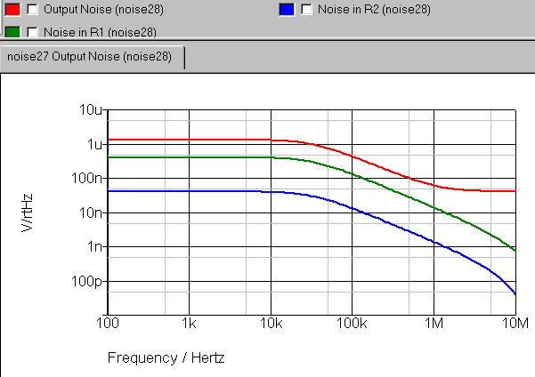
It is caused by the high value of the resistors used. SPICE simulators usually have the ability to probe “device noise”. This shows the contribution to the output noise from individual devices. Note that non-correlated noise sources are summed by “sum of squares” not simply added to get the total noise. If you probe the output noise of the circuit above and also the contribution from the two resistors you will see:

The output noise is almost totally dominated by the noise in R1 with R2 contributing very little. This is because the noise from R1 is multiplied by the closed loop gain of the opamp. While a 10MΩ resistor has 10 times the noise of a 100kΩ resistor, the gain is 100 so R1 noise dominates.
If the resistors are reduced in value but the gain is kept the same (100kΩ for R2, 1kΩ for R1) then the results are quite different:
Now the contribution of R1 to the output noise is lower and the actual amplifier noise is dominating. The overall output noise is around one third of the previous value. If you are designing discrete amplifier circuits (with transistors rather than opamps) then probing the device noise is equally useful and sometimes throws up some surprises – dominant noise from a device that you might not have expected to be a serious noise generator. This is often due to the amplification of the noise at a particular circuit node.
The post Noise simulation and analysis with SPICE appeared first on Analog IC Tips.
Filed Under: Software • simulation