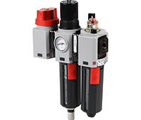
Available in many combinations, filters and regulators are a must-have on any machine. Other devices to perform functions such as energy isolation, lockout tagout and lubrication should also be considered.
By Chip McDaniel, AutomationDirect
All pneumatic motion requires clean and dry air with sufficient flow and pressure. The process of filtering, regulating and lubricating compressed air is known as air preparation, sometimes shortened as air prep. Manufacturing plants include air prep at centralized compressors, and additional air prep is beneficial at each machine’s point-of-use.

Figure 1: This air prep unit has many NITRA pneumatic components including filter, regulator with digital pressure switch, distribution block, lubricator, soft start/dump valve and manual shut off connected to a modular valve manifold.
The air prep system — often referred to as the FRL after the filter, regulator and lubricator that is often included in the assembly — is essentially the breathing mask on a machine, its personal protection equipment. Therefore, it is a must-have system, and it consists of many components. This article will discuss the components used in machine air prep systems and show how each is used, Figure 1.
Operating pressures
Air prep systems are typically assembled inline and come in a variety of port or body sizes. Most air prep systems fall in the range of 1/8-in. to 1-in. NPT female port sizes, with some exceptions. These systems are often modular in design, so when specifying an air prep system, it’s importation to match like-size devices for ease of assembly and use of accessories.
Generally, the pressure range of each pneumatic device is 20 to 130 psi, to match up with the common supply air pressure in a manufacturing facility, which is between these values. While a lockout valve may have a pressure range of 0 to 150 psi, other air prep devices such as filters, regulators and soft-start/dump valves require a minimum operating pressure to activate internal pilot and drain valves. The minimum operating pressure may be as low as 15 psi and as high as 35 psi, depending on the device.
Manual shut-off relief valves
Crushing, pinching, cutting, amputation and other injuries due to unexpected or automated machine motion often occur due to an employee’s failure to safely disable and isolate energy sources, and lockout/tagout the machine before performing service or maintenance work. Pneumatics is one of those energy sources, and because of the possibility of injury, OSHA and ANSI have important regulations regarding lockout/tagout control of hazardous energy and prevention of unexpected startup.

Figure 2: Rotating the red knob on this NITRA manual shut-off valve counterclockwise safely removes air from this conveyor zone eliminating pinch hazards during maintenance.
The air prep system not only protects the machine from debris and moisture, it can also protect operators from hazards by providing a means to safely remove pneumatic energy from the machine. The manual shut-off relief valve or a pneumatic isolation lockout valve provides removal of motion-causing pneumatic energy, along with a means to lock the valve in the off position as part of a lockout/tagout procedure. It shuts off upstream air pressure and relieves downstream air pressure to an entire machine or zone, Figure 2. Its oversized exhaust ports provide a quick pressure release, which can be very loud, so suitable silencers (mufflers) should be used, especially if ear protection is not required in the area.
These shut-off or lockout valves are typically either the first component connected to plant air at a machine, or the first valve following the FRL components. These valves use either a manually-rotated knob or push-pull activation, and both configurations can be locked out with a padlock. To aid visual identification, the knob should be red in color to indicate a safety device, like an emergency stop button.
It’s important to note that, even though the shut-off valve relieves air pressure, trapped air (energy) may still be present downstream from the air prep unit. The use of center-closed, three-position valves is just one of several examples of this, and it’s the designer’s responsibility to provide and document a manual or automatic sequence to remove such air for safe maintenance of the machine.
Pneumatic air filters
Filters are a critical part of an air prep system for removing both particulates and moisture. These filters use either a centrifugal or a coalescing design. The centrifugal types remove particulates and some moisture, while the coalescing types remove more water and also oil vapor. A dryer/refrigerator unit, not discussed here, may be required to remove larger amounts of moisture, and is installed just downstream of a plant air compressor.
A standard industrial air filter typically includes a replaceable 40-micron filter element mounted inside a polycarbonate bowl of various body sizes to accommodate different flow rates, with a metal bowl guard often included. For stricter filtration requirements, 5-micron filter elements are available. Finer, micro filters are available to remove particles 1 micron and below for special applications, but these require a courser filter upstream. Depending on usage, periodic replacement of a filter may work, but a downstream pressure switch — or better yet, a differential pressure switch measuring pressure across the filter, with its output monitored by a PLC — can be used to detect a clogged filter.
Regardless of the design, the filter can remove particulates, water and oil vapor — all of which are trapped in the filter — or accumulate at the bottom of the bowl as a solution that can be drained through a manual, semi-automatic or automatic drain. Manual drains require manually opening a drain plug to remove the accumulated liquid. Semi-automatic drains open each time compressed air is shut off, and an automatic drain opens when air is shut off or when the liquid in the bowl activates a float.
The type of drain used depends on the plant supply, application and environment. Very dry or low use equipment will work fine with a manual drain, but proper maintenance requires fluid level checks. Semi-automatic drains will work well in machines that are often turned off with air pressure removed. However, if air is always on or if water accumulates quickly, an automatic drain is the best choice.
Regulators
A regulator is often “set and forget” when used to supply compressed air at a consistent pressure to a machine, with a typical adjustable pressure range from 20-130 psi. Some processes operate at the low end of the pressure range, so low-pressure regulators are available to provide an adjustable range from zero up to around 60 psi. Regulators are also available to provide instrument air at common pressures, typically in the 3-15 psi range.
Because supply of air at constant pressure is critical to machine operation, a regulator with a locking pressure adjustment knob is required. An integral pressure gauge should also be included to help quickly identify actual air pressure. Another useful device is an adjustable pressure switch mounted downstream of the pressure adjustment device and monitored by the machine controller.
Pressure regulators have an input and output that must be connected correctly. The air must flow from input to output, and installing the regulator backwards will cause it to malfunction.

Figure 3: As the name implies, this NITRA combination filter/regulator combines both filter and regulator functions into a single, space saving unit.
The regulators should also have a relieving operation in most applications. With a relieving operation, if the pressure setpoint is reduced at the regulator, the regulator output will reduce downstream air pressure.
A combination filter/regulator includes all the features of a standalone filter and regulator in a single, space-saving device, Figure 3. Precision combination filter/regulators are also available with more precise pressure-regulating capability.
Lubricators
A lubricator adds lubrication as an oil mist to the pneumatic air supply instead of removing contaminates as a filter does. This lubrication can increase speed and slow wear in pneumatic devices such as air-operated hand tools including grinders, impact wrenches and torque drives. It also reduces leakage in operating components by sealing the rods, although it is not required to oil the seals on most modern pneumatic devices such as valves, cylinders, rotary actuators and grippers.
Lubricators are available in many port sizes and the lubrication rate can be adjusted. To assist with maintenance, a sight gauge is included, and the oil can be added while the devices are under pressure in most cases. The mist level must be properly adjusted and the oil level maintained, and the proper oil (typically light viscosity oil such as SAE 5, 10 or 20 with rust and oxidation inhibitors added) must be provided. Also, the device in need of lubrication must be close enough to the lubricator for the oil mist to remain suspended in the air. Too much oil may cause an oil mist in the facility, along with oil puddles and slippery floors.
Soft start/dump valves
The soft start/dump valve is an important device for operator safety, and typically includes a 24 Vdc or a 120 Vac solenoid controlled by an emergency stop, or by guard or light curtain safety circuits. It dumps motion-causing pneumatic energy by shutting off upstream pressure and relieves downstream pressure when de-energized during a safety event. When the circuit is re-energized, the solenoid gradually increases air pressure downstream. This keeps tooling from moving too quickly and banging at startup.
This valve is mounted downstream of the FRL, typically feeding air to motion-causing solenoid valves. The dump valve exhausts pressure quickly, so a high-flow muffler should be used to attenuate the sound. An adjustable flow control is provided to control how fast the air pressure returns to the set pressure.
Air prep accessories
All the pneumatic air prep devices above are provided with a mounting bracket for stand-alone applications, or the mounting accessory can be purchased separately. Air prep systems are often modular in design which allows individual shut off, filter, regulator, lubricator and soft start/dump valves to be easily field assembled with other components.
Assembly brackets and adapters are often required when connecting these modular devices to create a combined unit. These adapters include U-, L-, and T-brackets, each of which has one or more mounting tangs. Air distribution blocks are also available for installation between pneumatic components.

Figure 4: Total air prep systems are about half the size, weight and cost of systems assembled from separately purchased components.
Conclusion
Total air prep (TAP) systems are available as an alternative to specifying all the air prep components separately. These all-in-one systems include the filter, regulator, shut off/dump valve, soft start, electric shut off, pressure switch and indicator. A TAP is about half the size, weight and cost of an air prep system assembled from separately purchased components, Figure 4.
With a better understanding of pneumatic air prep components and their use, both machines and operators can be protected. To summarize, a manual shut-off relieve valve and soft start/dump valve is required to control, isolate and remove compressed air from the machine or system. As the air flows to the system, a filter, regulator and lubricator are used to prep it for use.
Figures all courtesy of AutomationDirect.
Filed Under: Pneumatic equipment + components, Filters (mechanical) for air + fans, Flanges • supports • mounts • brackets


