Doug Hedges, the President of Sintavia, is a mechanical engineer and an additive manufacturing professional. His experience includes part manufacture approval (PMA), designated engineering representative (DER) repairs, OEM part manufacture and design, and large-scale jet engine maintenance, repair, and overhaul (MRO).
Recently, Doug set out to prove the ability to additively manufacture aerospace replacement parts. Doug’s goal was to produce optimized designs of aerospace brackets that meet or exceed the existing bracket’s mechanical properties while decreasing the overall weight of the parts. To do this, Doug relied on a component he encountered in a previous career. The component is based on an aftermarket aviation part for a low pressure turbine. This particular part is used 12 times on each engine.
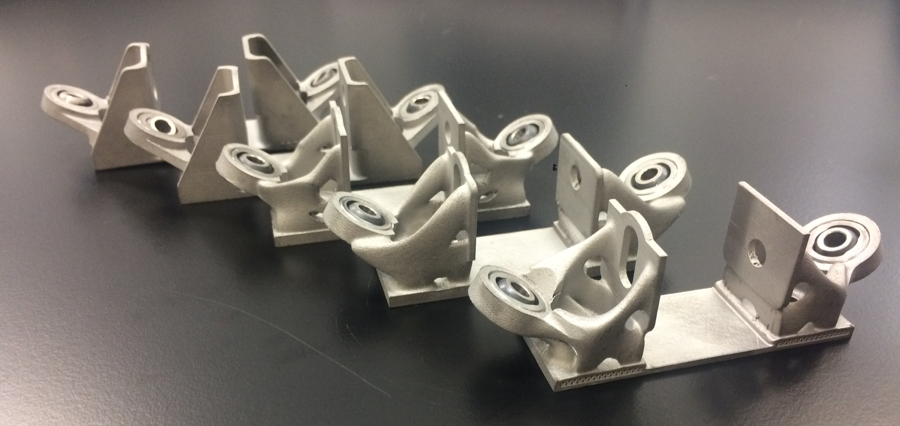
Image courtesy of Sintavia
Noted Doug, “My goal is to streamline maintenance, repair and overhaul organizations using generative design and additive manufacturing. If these organizations adopt these technologies, they can see many benefits including streamlined (internal) fabrication, easier make vs. buy decisions, virtual inventory, replacement of obsolete or discontinued parts, and improved performance characteristics of the parts can be achieved including decreased weight, increased strength, and increased fatigue characteristics.”
Initial aerospace bracket design.
For Doug to create this proof of concept he used many of the tools that Sintavia has on-site to design and manufacture the part. SINTAVIA is a global leader for independent metal additive manufacturing (AM) for the aerospace and defense, oil and natural gas, automotive, and ground power generation industries. The company’s in-house equipment includes six high-speed printers from four of the largest global OEMs, a hot isostatic press, a vacuum heat treatment furnace, an industrial CT scanner, a wire EDM, a full complement of mechanical testing equipment (including high temperature tensile, fatigue, and creep testing), a full metallurgical laboratory (including a scanning electron microscope and optical emission spectroscope) and a micro powder lab.
The first step for Doug’s proof of concept was to capture the geometry of the original part using a blue light scanner. Once the scan was complete, Doug and his team created a high-fidelity CAD model to the exact specs of the original geometry.
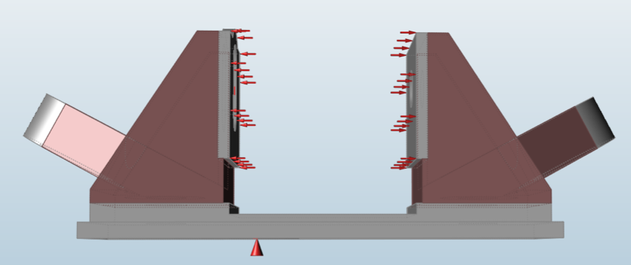
solidThinking Inspire optimization results
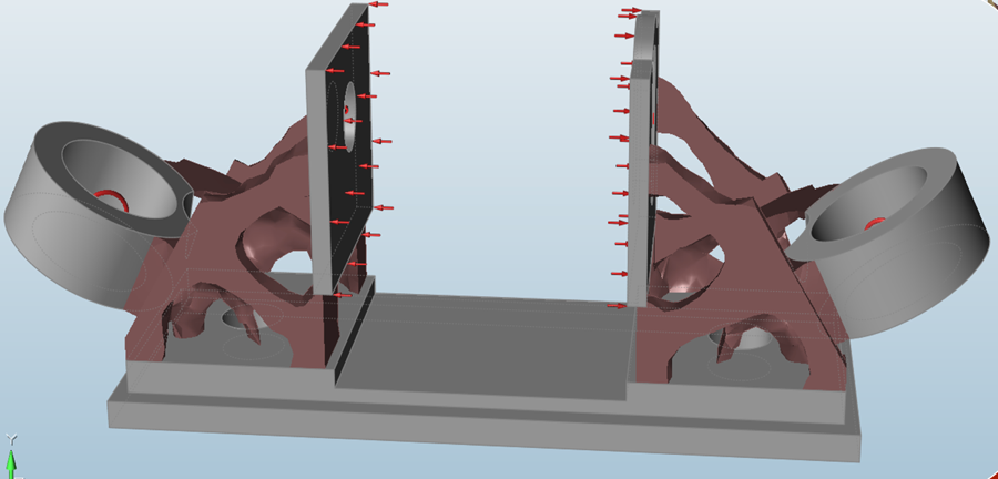
“Next we determined all of the loading conditions that the part would incur during its usage,” said Doug. “Using solidThinking Inspire, we applied these to the model and after separating all design and non-design spaces, we ran multiple optimization iterations on the part. These included multiple rounds with modified design spaces, testing of different compression, factory of safety, and so on. Finite element analysis was then run on the results to compare and determine the best optimization iteration to move forward with.”
Once a final Inspire optimization result was selected from the multiple options, Doug and team used the PolyNURBS tools inside of solidThinking Evolve to refine the optimization into its final geometry.
After the final optimized geometry was created, the team used the SLM Systems’ 280 twin-laser machine, coupled with Inconel 718 powder to produce the part. Post manufacturing was also completed on the part to ensure it was ready for testing and ultimate use. First, the team used in-house vacuum heat treatment on the part. Then they removed the part from the build plate using EDM (electrical discharge machining). Additional steps included support removal, sand blasting and polishing, and hot isostatic pressing to eliminate any voids or cracking in the part.

Final print of the parts with SLM 280 Twin Laser
The team has since run multiple tests on the part including proof testing with a load of 5000 lb, fatigue testing, metallurgy testing, and more. In all tests, the optimized printed part outperformed the original. The new part has a 3x fatigue life and less porosity than the original, all while weighing in at ~15% lighter.
Doug plans to further optimize this part, as well as work on other parts that can be optimized for additive manufacturing. “With the engine turbine part, I want to continue to work to further reduce the mass. We also plan to strengthen the collar, and may even work on a design with integrated bearings.”
solidThinking
solidthinking.com
![]()
Filed Under: Aerospace + defense, 3D printing • additive • stereolithography, Flanges • supports • mounts • brackets, Make Parts Fast