 A prosthesis or prosthetic implant is an artificial device that replaces a missing part of the body, which might have been lost due to accident, trauma, disease, or congenital disorder. An orthopedic prosthetic is an artificial limb designed to substitute the missing body part of a patient. It is intended to restore a degree of normal function, thus providing precise movements and efficient operation.
In the past, a hand amputee would have been asked to use a hook prosthesis that had limited functions and carried a significant amount of social stigma. However, in today’s society, a hand amputee can expect a replacement hand that replicates a whole host of normal hand functions.
Upper limb prostheses can be categorized into three main categories: passive devices, body-powered devices, and externally powered (myoelectric) devices.
A myoelectric prosthesis uses the electrical tension that is being generated every time a muscle contracts. This tension can be captured from the voluntarily contracted muscles through electrodes applied on the skin to control prosthesis movements, such as elbow flexion/extension, wrist supination/pronation, (rotation), or opening/closing of the fingers. A prosthesis of this type uses the human body’s residual neuromuscular system control the functions of an electric-powered prosthetic hand, wrist, elbow, or foot.
Most prosthesis manufacturers use EMG (electromyography) signals for actuation. In 1919, G. Schlesinger defined six basic ways of grasping as shown in the figure below:
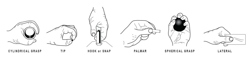
Based on these basic prehensions, price, and functionality, manufacturers can choose the appropriate type of mechanism and determine the number of motors needed in these actuation mechanisms. It can be a fully articulated arm or a semi-articulated arm. In a fully articulated arm, manufacturers use five motors for the actuation of all five fingers to achieve multiple degrees of movement. This provides better flexibility to the end-user for achieving almost all major configurations of the arm.
In a semi-articulated arm, a single motor is used for the actuation of two or three fingers (the middle finger, ring finger, and little finger). Individual motors are provided for actuation of the index finger and thumb. This helps reduce cost and simplify design. Naturally, there are limitations to the degrees of movement. It is the major movements used frequently in day-to-day life that are the focus in these designs.
Requirements for a Good Prosthesis
- Functionally efficient
- Durable
- Comfortable
- Lightweight
- Low maintenance
- Long battery life
- Aesthetically pleasing
Standard motion solutions for prosthetic hands
Coreless brush DC motors, being highly efficient, reliable, and cost-effective, are a common solution for prosthetic arms. A coreless brush DC motor, with its incorporated gearbox, operates at low noise — an understandable requirement for myoelectric prosthetic arm users. For prosthetic hands, the typical requirement for motors is 50 mNm @ 150 rpm to 100 mNm @ 50 rpm. A lighter motor reduces the overall weight of prosthetic hands and allows users to move each finger independently with minimum effort in single finger actuation designs. The design of the coreless brush DC motor also offers high power density. It suits the compactness and portability requirement of prosthesis applications.
Some of the lower cost myoelectric semi-articulated hand prosthesis manufacturers use one motor for four single-finger actuations. Here, the degree of freedom is two; one for movement of the four fingers and one for the thumb’s manual movement. The typical torque requirement in this design can range between 300 mNm @ 1500 rpm and 400 mNm @ 1000 rpm.
For accurate positioning and motion control, a suitable encoder is recommended for the motor and gearbox. Motors with integrated gearboxes and encoders enable the user to move fingers more nimbly to grasp objects. Magnetic encoders provide a high degree of accuracy necessary for prosthetics applications that require incredibly accurate positioning with closed-loop motion feedback. Precise position is required to grip objects like an egg with the dexterity required to prevent breakage.
Motor and gearbox selection is a direct contributor to the success of the application. The solution chosen should offer sufficient torque and speed (power) to ensure proper holding force and linear speed necessary for grasping. The type of mechanism used for finger actuation should also be a deciding factor in motor selection.
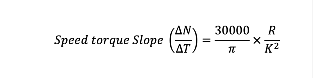
Motor regulation (R/K2) is a critical parameter of the motor which defines speed-torque characteristics. Lower motor regulation results in a more powerful motor, but it is important to remember — as torque (load) increases, speed decreases. The speed drop rate is less with better motor regulation. Good motor regulation provides high power density, which leads to fewer power losses and better efficiency.
If motor regulation is a critical parameter of the motor, then efficiency is the critical parameter for new-generation prosthetic hands. Here, smaller and lighter weight batteries are considered — high-efficiency results in fewer power losses and less current consumption, increasing battery life.
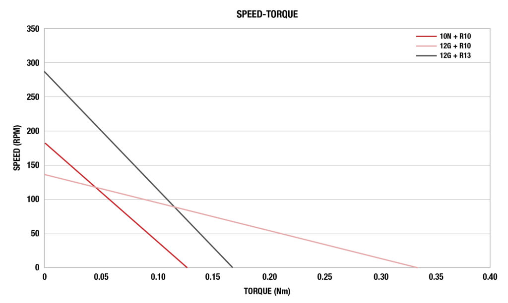
The selection of a motor and gearbox depends heavily on torque/speed requirements and size constraints of the application. In the chart above, we’ll use a few Portescap DC motors to compare. As you can see in the chart, the slope of the 10N motor + R10 gearbox with ratio 64 is nearly the same as the 12G motor + R13 gearbox with ratio 30.2, although the 12G + R13 provides a wider range of torque and speed. This design means that by increasing size, we can increase the power of the motor-gearbox composite. The slope of the 12G motor + R10 gearbox with ratio 64 is lower. Hence, it operates at a higher working torque, though at a lower speed.
Integrated solutions for prosthetic hands
Average operational requirements for prosthetic arms can look something like this:
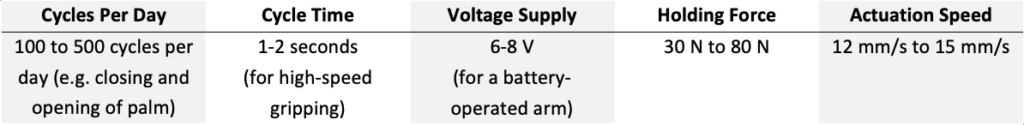
For 180°transmission with a lead screw mechanism, the torque and speed requirement of motor-gearbox composite depends on the type of lead screw (no. of start, lead, thread type).
Often, a customized solution is needed to meet specific application requirements. An integrated design can best suit the size and weight constraints of each application. An optimized design can withstand the specific axial forces necessary for the application. An example of an integrated solution prototype is shown below.
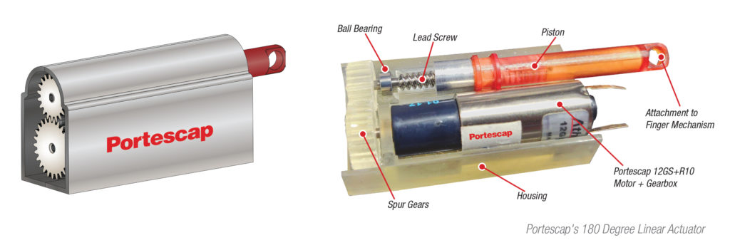
In this example prototype, the mechanism consists of a motor that transfers the rotary motion to a lead screw using a spur gear pair. The lead screw is attached to one spur gear and transfers motion to the piston, which has internal threads. The piston moves forward and backward due to the screw and nut mechanism between the lead screw and the piston. This linear motion of the piston is what creates finger actuation.
Portescap’s prototype with the 12GS+R10 motor-gearbox composite was tested at 1V, and the composite provided a linear speed of 7 mm/s at no load with an electric current consumption of 15 mA. Linear speed can be increased by increasing the voltage. The linear speed of the actuator depends on the weight of the object the user is handling. No-load linear speed of an actuator is associated with the motion of a finger without an object. Higher linear speeds allow the user to grasp objects quickly. Based on the calculations, the designed load for this actuator is 60 N. The force and speed depend on one’s choice of motor, gearbox, and the size of the leadscrew used for the linear actuator. Naturally, the size of the linear actuator varies from application to application. The low current consumption of the linear actuator provides a longer battery life.
You’ll also want to consider if your application requires motion-feedback solutions, including linear actuators, that can be customized precisely for the output needed and can fit inside the actuator so that the operation can be controlled accurately. The piston’s linear motion can be controlled by using a linear potentiometer or a linear magnetic encoder.
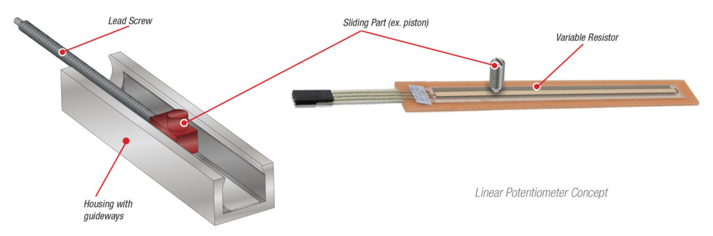
A linear potentiometer works on principles based on calculating the variation of the resistance produced by the displacement of the object inside the electric circuit. It consists of a spring-loaded head, and it produces a sufficient amount of analog output without using the amplifier. The benefit of using a potentiometer feedback system in a linear actuator is that the controller does not have to track the position of the piston. It offers the absolute position of the piston at any given moment. It is suitable for low-speed requirements and is less costly. As compared with magnetic encoder, it offers 50% of life.
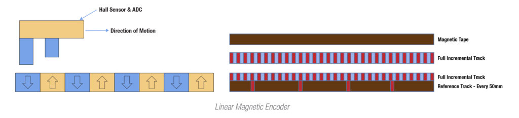
A linear magnetic encoder is a hall-sensor-based encoder that detects the magnetic field. There is no friction between any parts in the sensor because the parts are not in contact with one another. In linear actuators, the magnet attaches to the piston, and the two hall sensors are placed near the magnet. As the magnet (piston) moves, the hall sensor detects the magnetic field. This produces a pulse, which is used by the controller for keeping track of the position. The two hall sensors, which are offset from each other, produce two overlapping pulses. The overlapping signals determine the direction of travel.
For encoders, even a slight misalignment of the shaft reduces accuracy and increases hysteresis losses. Linear magnetic encoders have more accurate positional measurement, increasing reliability for high-speed applications and longer life. Magnetic encoders offer a consistent signal throughout the life of the linear actuator. They provide exact increments of positional data. The controller keeps the track of the position, offering a ‘home detection’ functionality to reset position to a known state.
Portescap
portescap.com
Filed Under: Medical-device manufacture