Design World

  • Home
  • Technologies
    • 3D CAD
    • Electronics • electrical
    • Fastening & Joining
    • Factory automation
    • Linear Motion
    • Motion Control
    • Test & Measurement
    • Sensors
    • Fluid power
  • Learn
    • Ebooks / Tech Tips
    • Engineering Week
    • Future of Design Engineering
    • MC² Motion Control Classrooms
    • Podcasts
    • Videos
    • Webinars
  • LEAP AWARDS
  • Leadership
    • 2022 Voting
    • 2021 Winners
  • Design Guide Library
  • Resources
    • Subscribe!
    • 3D Cad Models
      • PARTsolutions
      • TraceParts
    • Digital Issues
      • Design World
      • EE World
    • Women in Engineering
  • Supplier Listings

Research Could Lead To Better, Safer Wings

By NASA | October 27, 2017

Share

A uniquely instrumented wing will allow researchers to investigate advanced methods of monitoring flight loads, which could lead to improved flight safety.

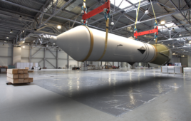
The Passive Aeroelastic Tailored, or PAT, wing is expected to arrive later this year at NASA Armstrong Flight Research Center in California. The uniquely designed composite wing is lighter, more structurally efficient and has flexibility compared to conventional wings, said Larry Hudson, Armstrong Flight Loads Laboratory chief test engineer. 

The layout of the fibers that make up the PAT wing are specially tailored and the performance of that design will be validated during these tests. Future commercial aircraft could use this wing building design to maximize structural efficiency, reduce weight and conserve fuel.

 “It’s called a passive tailored wing because the structural efficiency is contained within the construction of the wing, it’s not an active system that is controlling the structural efficiency of the wing, it’s the composite layout,” Hudson explained.

The PAT wing was developed by Aurora Flight Sciences of Virginia and fabricated at the company’s manufacturing plant in Mississippi. The project is funded by the Aeronautics Research Mission Directorate through the Advanced Air Transport Technology project.

Until the PAT wing arrives, loads lab staff are working on the Calibration Research Wing, or CREW, in a similar test fixture for proficiency testing. CREW will be used as a pathfinder for the PAT wing. The two wings share similar instrumentation layout and collect similar data, which is why the CREW wing is a valuable hands-on dry run to collect data, learning how to analyze data and complete calibrations. 

One of the major differences in the test architecture is the overhead loading system required to handle the significantly larger wing tip displacement inherent with the longer and more flexible PAT wing.

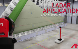
Another research item is the extensive use of the Fiber Optic Sensing System, or FOSS, technology. FOSS will enable faster and more economical loads calibration of the wings in the future. FOSS uses hair-like optical fibers that are bonded to the wing’s surface and can provide thousands of strain measurements to determine wing shape and distributed load.

 “We will look at the limits of FOSS and how to maximize its use to help reduce the cost and schedule of loads calibration testing,” Hudson said.

Davis-Monthan Air Force Base in Arizona provided the MQ-9 (same kind of aircraft as NASA’s Ikhana) wing that serves as the CREW testbed. In 2007, Ikhana was the first large aircraft to fly with FOSS at Armstrong.


Filed Under: Aerospace + defense


Related Articles Read More >

Mars helicopter receives Collier Trophy
Flexible rotary shafts to power Delta Airlines’ engines powering their first Airbus A321neo aircraft
Ontic acquires Servotek and Westcon product lines from Marsh Bellofram
Flexible rotary shafts support thrust reverser on 150 LEAP 1-A turbofan engines

DESIGN GUIDE LIBRARY

“motion

Enews Sign Up

Motion Control Classroom

Design World Digital Edition

cover

Browse the most current issue of Design World and back issues in an easy to use high quality format. Clip, share and download with the leading design engineering magazine today.

EDABoard the Forum for Electronics

Top global problem solving EE forum covering Microcontrollers, DSP, Networking, Analog and Digital Design, RF, Power Electronics, PCB Routing and much more

EDABoard: Forum for electronics

Sponsored Content

  • Industrial disc pack couplings
  • Pushing performance: Adding functionality to terminal blocks
  • Get to Know Würth Industrial Division
  • Renishaw next-generation FORTiS™ enclosed linear encoders offer enhanced metrology and reliability for machine tools
  • WAGO’s smartDESIGNER Online Provides Seamless Progression for Projects
  • Epoxy Certified for UL 1203 Standard

Design World Podcasts

July 26, 2022
Tech Tuesdays: Sorbothane marks 40 years of shock and vibration innovation
See More >
Engineering Exchange

The Engineering Exchange is a global educational networking community for engineers.

Connect, share, and learn today »

Design World
  • Advertising
  • About us
  • Contact
  • Manage your Design World Subscription
  • Subscribe
  • Design World Digital Network
  • Engineering White Papers
  • LEAP AWARDS

Copyright © 2022 WTWH Media LLC. All Rights Reserved. The material on this site may not be reproduced, distributed, transmitted, cached or otherwise used, except with the prior written permission of WTWH Media
Privacy Policy | Advertising | About Us

Search Design World

  • Home
  • Technologies
    • 3D CAD
    • Electronics • electrical
    • Fastening & Joining
    • Factory automation
    • Linear Motion
    • Motion Control
    • Test & Measurement
    • Sensors
    • Fluid power
  • Learn
    • Ebooks / Tech Tips
    • Engineering Week
    • Future of Design Engineering
    • MC² Motion Control Classrooms
    • Podcasts
    • Videos
    • Webinars
  • LEAP AWARDS
  • Leadership
    • 2022 Voting
    • 2021 Winners
  • Design Guide Library
  • Resources
    • Subscribe!
    • 3D Cad Models
      • PARTsolutions
      • TraceParts
    • Digital Issues
      • Design World
      • EE World
    • Women in Engineering
  • Supplier Listings