By Allan Conway, Nexen Group, Inc.
A roller pinion system is a linear drive approach that combines the best features of ball screws, rack and pinion, belt drives and linear motors while eliminating many of their short comings.
To meet the goals of designing machines and equipment that are faster, more precise, and require less maintenance, commonly chosen options include ball screws, linear motors, and servo controlled linear drive systems. But another option to consider is the roller pinion system (RPS), an innovative approach to linear motion.
Linear drive systems typically consist of ball screws, rack and pinion, belt drives, and linear motors. While these systems have several desirable features, depending on the application you may have to deal with backlash, low rigidity, cumulative error, thermal creep, limited length, low speeds, low force capability, vibration, and noise.
The roller pinion system, on the other hand, is a linear drive concept that combines the best attributes of existing technologies while eliminating most of their shortcomings.
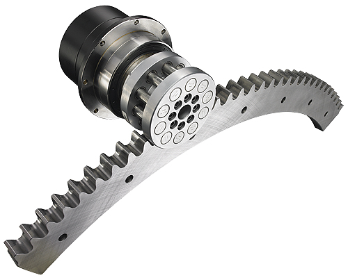
Visually similar to involute gearing, the roller pinion system functions differently. The key is the roller pinion. Instead of formed metal teeth, the pinion is comprised of rolling pins; each supported by two needle roller bearings. This allows friction-free motion as the rollers engage a tooth profile designed to perfectly match the path of the pinion. The friction free meshing also allows the pinion to be preloaded into the rack, eliminating all mechanical clearance.
The bearing supported rollers eliminate the sliding friction of traditional rack and pinion systems, converting rotary motion to linear motion with 99% efficiency.
Targeting specific applications
Five versions of the roller pinion system are available for unique and challenging motion control demands. These versions include the Standard, Premium, Endurance, Universal and Stainless Steel Universal Rack. Each has distinct capabilities that make it best for specific industries and applications. In addition, each model can be sized to meet exact machine specifications.
The models are available with corrosion resistant surface treatments or made from 17-4 stainless steel for difficult applications. Pinions are available in shaft mount with a keyless mechanical compression bushing or ISO 9409 flange mount versions for machine design flexibility. The flange mount pinions ease reducer selection and mounting, and allow the use of pinion preloaders.
Racks can be chosen for specific application needs. For example, the Standard Rack is heat-treated, features 50-micron accuracy and offers a high load carrying capacity. These features suit motion control applications for injection molding machines and laminating machines.
In harsh environmental conditions, the Premium Rack is protected from corrosion and does not require lubrication, making it suitable for applications such as honing machines, aircraft assembly, five axis ceramic and carbon fiber profiling machines.
For intricate applications requiring pinpoint accuracy, the Endurance Rack was developed for counting, sorting and bagging machines.
In applications with strict sanitation regulations, the Stainless Steel Universal Rack resists extreme corrosion found in food grade applications, such as packaging and filling machines. For economical, high-quality motion control, the Universal Rack features medium hardness and ensures the precision necessary for glass and pipe cutting applications.
Positional accuracy
The RPS rack uses a modular concept with only two standard factory lengths per size that can be joined to create runs of any length. Full lengths are around one meter and half-lengths around one-half meter depending on tooth pitch. Shorter rack segments can be made by cutting the rack.
Positional accuracy is from 30, 50 and 80 microns. Typically, the Premium rack offers accuracy of 30 microns, while Standard, Universal and Stainless Steel Universal racks feature positional accuracy of 50 microns and the Endurance rack is capable of positioning precision to 80 microns. To transfer the positional accuracy to the following rack segments, a special tool was developed that uses the rack tooth profile to set the rack spacing rather than simply butting racks end to end. The alignment tool uses two teeth on each rack averaging out some of the transferred error. This small transferred error is ± each time and statistically trends to zero, so an infinitely long run would, in theory, have zero cumulative error. This feature allows runs of virtually any length without loss of system accuracy. In many cases, a linear encoder is no longer needed and the servo encoder can be relied on, reducing cost and complexity.

This positional accuracy graph shows precise linear encoder and rotary encoder data from the pinion shaft. The periodic wave pattern shows that while there is some error, it is not cumulative.
The graph above shows the positional accuracy based on very precise linear encoder and rotary encoder data on the pinion shaft.
Looking at the wave pattern you will see individual spikes representative of individual pin and rack meshing error and a general periodic wave pattern representing the error in the pinion body that repeats with each revolution. As you can see, the error bar lines are horizontal showing no cumulative error. This would continue throughout any individual rack segment or run length.
The graph below illustrates repeated returns to the same locations from one direction and both directions. As you can see repeatability from one direction is better than 2.6 μm and from both directions better than 5.8 μm. The difference between these two numbers is the backlash in the system and is less than 3.2 μm. This will hold true over nearly any length run.

This graph shows repeated returns to the same locations from one direction and both directions. The difference between the repeatabilities is the backlash in the system, which is less than 3.2 μm over any length run.
The RPS system is capable of speeds up to 11 m/s (36.1 ft) making it the fastest mechanical linear drive system second only to linear motors. Even at these speeds, the low friction design results in minimal heat and wear on components.
Each individual RPS system has a maximum speed limitation that is a function of the specific needle bearings used in the roller pinion. In practice, the roller pinion performs at faster rates than the other components in the system, such as linear bearings and utility carrier—delivering more speed capacity than required by the machine.
The rack and pinion body is made from carbon steel. The rack teeth are heat treated for wear resistance. In many applications, liquids and corrosive materials would pose a problem for an unprotected steel product. Stainless steel is not a viable option since it has less strength, and would compromise the unit’s performance.
Due to extremely tight manufacturing tolerances, the RPS requires a coating that does not build up on the surface or quickly wear away. The protective surface treatment is called Raydent. The Raydent treatment is a cryogenic process that permeates the metal surface and molecularly bonds with the steel forming a ceramic chrome layer with minimal surface buildup. It is durable and resistant to acids, alkalis, and various solvents. It will not flake or rust if scratched. If a thin piece of metal is treated with Raydent and then sharply bent in half the coating will not be compromised.
Due to the smooth way the rollers engage the rack teeth the RPS system generates low noise and vibration. Eliminating sliding friction allows the system to operate more quietly than standard rack and pinion. The system is whisper quiet at low speeds and less than 75 db at full speed. Typically, the guiding system, servomotor, and reducer generate more noise than the RPS system.
The RPS system has a long operating life, yet requires little maintenance. The pinion consists of 10 or 12 needle-bearing supported rollers that are sealed and lubricated for life. The rack is lubricated with a high performance light grease at installation and then every six months or 2 million pinion revolutions. In special applications the RPS system can be run lubrication free as long as the speed is less than 30 m/min.
The Premium and Endurance racks do not require lubrication if performing at 0.5 m/s or under, and only small amounts of lubrication are necessary for Standard and Universal Racks.
Because of the lubrication requirements, the RPS system has low particle emissions making it suitable for applications such as clean rooms, food processing, coating operations and pharmaceutical production. Even with very low maintenance the RPS system provides 60,000,000 pinion revolutions of life at its rated performance. That’s 9.6 – 28.8 million meters (3.2 – 95.5 million feet) when properly installed and maintained. The RPS system continues to operate beyond this point with diminishing accuracy.
No lubrication can also be beneficial in applications such as cutting, milling and routing. Contaminants are less likely to stick to the rack, reducing the creation of an abrasive paste that accelerates wear in mechanical systems.

Many linear drive technologies are specified by starting with a life consideration with the product size increasing with the life requirements. The RPS system selection process does not take life into consideration and is primarily based on load.
Installing an RPS system is comparable to the installation of precision profile guide rails. The rack should be placed on a step in the machine bed to provide full bottom support and a back plane for bolting it in place and to ensure straightness especially when joining rack sections.
Once the pinion is mounted, and its axis is properly positioned parallel to the rack tooth faces and fully engaged in the rack, a small preload is applied to take up the clearance in the pinion roller bearings. A high degree of rack mounting surface flatness is desirable, but more important is the parallelism between the guiding system and the RPS so pinion preload is neither lost nor becomes excessive. Each rack features the same simple installation process.
Nexen Group, Inc.
www.nexen.com
Filed Under: Ballscrews • leadscrews, Encoders • linear, Encoders (rotary) + resolvers, LINEAR MOTION, MECHANICAL POWER TRANSMISSION, Motion control • motor controls


I am looking to build a linear drive to carry a MIG welding torch. Length of weld is 900mm. to 1200mm. (3′-4′)
Control would be manual, with the operator pressing a button to start the welder and the linear drive at the some time and releasing the button to stop.
Any advise would be welcome along with pricing.