By Gary Shelton, Principal Design Engineer, Exlar Corp., Chanhassen, Minn.
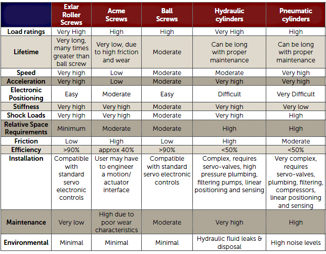
The choice of hydraulic/pneumatic or mechanical actuators always depends on the application, but if application factors are equal, the roller screw actuator has some advantages.
Roller screw actuators have several advantages over hydraulic or pneumatic actuators for many applications, especially those involving heavy loads and fast cycles. For example, the controls are simpler, eliminating the complex system of valves, pumps, filters and sensors that make up hydraulic and pneumatic systems. Other benefits include a small system footprint, long functional life and low maintenance requirements. And because roller screw systems don’t require high-pressure fluid, they reduce noise levels and are not subject to potentially hazardous fluid leaks.
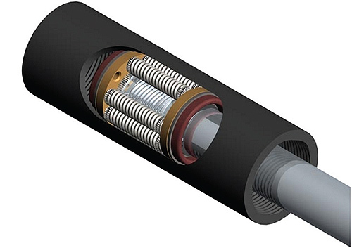
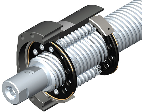
Rollers screws come in two basic kinds of configurations; the inverted roller screw mechanism, top, and the standard configuration roller screw, bottom.
Roller Screw Technology
Roller screws convert rotary torque into linear motion, similar to acme screws or ball screws. But roller screws can turn considerably faster and cycle more frequently than both acme and ball screws, making them an ideal fit for demanding, continuous-duty applications. Similarly sized roller screws are more efficient than acme screws and can carry larger loads than ball screws, handling loads up to 779,000 lbf.
The difference in performance is due to the design for transmitting forces. The number of contact points in a ball screw is limited by the ball size. In roller screw systems, multiple threaded rollers are assembled in a planetary arrangement around a threaded shaft, which converts a motor’s rotary motion into linear movement of a shaft or nut. The rollers feature radiused flanks that deliver point contact, similar to balls on a raceway, with only the radius near the point of contact included as part of the profile. This design allows a larger radius with additional contact points to fit into the existing space, lowering the stresses within the system and lengthening its functional life. Because the number of contact points is greater, roller screws have high load-carrying capacities, as well as improved stiffness. This typically means that a roller screw actuator takes up less space in order to meet a designer’s load requirement than a similarly sized ball screw.
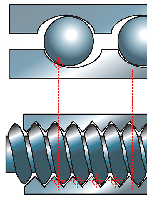
Roller screws are designed to have larger radii at the point of contact, meaning that more contact points will fit within the same relative space. This lowers stresses and lengthens functional life compared to a comparably sized ball screw system, top.
High load capacities mean that roller screws have some major advantages in service life. For instance, in a 2,000 lbf average load application applied to a 1.2 in. screw diameter with a 0.2 in. lead, a roller screw will have an expected service life that is 15 times greater than a ball screw. Typical ball screw speeds are limited to 2,000 rpm and less due to the interaction of the balls colliding with each other as the race rotates. In contrast, the rollers in a roller screw are fixed in a planetary arrangement by a journal and gears at the ends, so they do not have the same speed limitations. Hence, roller screws can work at 5,000 rpm and higher, producing comparably higher linear travel rates.
Versatile nut options let you balance between backlash and load capacity demands and cost trade-offs. Some common nut configurations are the single nut, split nut and double nut designs. The most common configuration, the single nut, has a long service life and low backlash under 0.001 in. In split nut designs, the nut is split transversely and a precision-ground spacer sits between the front and back halves. The split nut configuration effectively eliminates backlash and also reduces the dynamic load rating by about 38%. As the name implies, the double nut arrangement uses two nuts preloaded against each other on a single screw. This design offers similar life expectancy as a single-nut design as well as decreased backlash, but typically costs more than a single-nut configuration.
Roller Screw Size Specification
Roller screw variables include the diameter, lead and sealing. When preparing the component specification, be sure to take into consideration the budget, maximum linear speed, maximum load, maximum stroke, necessary precision level, tolerance to backlash, the contaminants present and the needed level of protection.
A few key calculations help determine the ideal parameters for an application. For example, roller screw nut speeds cannot exceed their mechanical speed limit, which is dependant on the screw diameter and the lubrication method. Systems lubricated with oil should not exceed 140,000/do, while grease-lubricated roller screws systems shouldn’t surpass 90,000/do.
In high-speed roller screw applications, the roller screw shaft typically sets up natural frequency vibrations, which should be taken into account by calculating the critical speed. This speed is determined by the screw diameter, length, loading direction and bearing arrangement. The rotational speed of a roller screw should be kept below the critical speed, defined as:
ncrit = 86.4 x 10⁶dofs / l2
where:
ncrit = critical rotational speed under zero axial load (rpm)
do = screw diameter, in. (mm)
fs = support bearing factor
l = screw’s length, in. (mm)
Another phenomenon to avoid is buckling. Buckling occurs when the compressive load on a screw’s shaft is too great for its diameter. The buckling force is determined by the screw length, diameter and type of bearing supporting the screw. The compressive load should be less than the buckling force, defined as: Fb = 81.3fbdo4 / l2
where:
fb = buckling force, kN
Fb = buckling force bearing factor
Another factor to consider is the motor size. A motor is selected by calculating the required torque as a function of load on the system and lead of the roller screw and comparing it to available motors and power transmission components. For applications that require a specific motor, roller screws with a lower or faster lead, belt or gear reductions can be configured into the system.
Protection and Maintenance
While correctly specified and maintained rollers screw systems can still fail from metal fatigue or abrasion of the thread flanks, other failures can typically be prevented. For optimal performance and life, roller screws, like other lead screws, should be well lubricated and must tolerate contaminants including abrasives, metal chips and non-lubricating fluids.
Although the friction created by the rolling screw design is minimal compared to sliding friction, it can still cause heat build-up, which can eventually lead to a costly failure. Lubricants should be used to dissipate heat in order to avoid wear and premature failure. In general, roller-screw life can be increased by regular grease and oil replenishment. Maintenance intervals depend on the screw size and operating conditions. Typically KP (DIN 51825) consistency two bearing grease should be applied. Some applications with higher duty cycles may need a high-performance gear oil with EP additives. Lubrication rates vary according to the screw diameter, number of rollers and the amount of heat to be dissipated.
Providing sufficient protection against contaminants is also critical to long functional life. For instance, if metal chips get into the nut assembly, the roller screws may grind them into a lapping compound, which will cause spalling and eventual catastrophic failure. Shaft wipers, bellows, shrouding and enclosures protect roller screw components from environmental contaminants, and should be selected according to specific application requirements. For example, wipers can be added to the front or back of the nut to scrape particulates from the threads throughout the screw stroke. Additionally, force tubes that house roller screws keep lubricants in, while preventing contaminant infestation. Force tubes with IP67 ratings are available in a wide array of mounting options.
Improper loading is another possible cause of roller screw failure. As a general rule, lead screws do not tolerate applied moments or side loading, so high-precision slide rails should be used to carry these loads and make certain that loading on the nut is co-axial to the lead screw.
Although roller screws may have a higher initial cost than alter-native motion actuation systems, they usually provide significant cost savings in the long run. In fact, a properly specified and maintained roller screw system typically costs half that of the cumulative cost of ball screw systems, since they do not need to be replaced or
maintained as frequently.
Discuss this on the Engineering Exchange:
Exlar Corp.
www.exlar.com
::Design World::
Filed Under: Factory automation, Actuators, AUTOMATION, Ballscrews • leadscrews, Hydraulic equipment + components, Pneumatic equipment + components, Screws • nuts • bolts, FASTENING • JOINING • locks • latches • pins, MECHANICAL POWER TRANSMISSION, Motion control • motor controls

Hello:
I’m plant manager of a friction operation from Federal Mogul corporation.
We’re interested in alternative to replace hydraulic presses for this kind of actuators.
I would like to have a conference call to define opportunities for this project.