By Helge Hornis, Ph. D. – Manager Intelligent Systems Group – Pepperl+Fuchs
The Safety at Work technology can now handle more applications thanks to its ability to work with stand-alone safety controllers.
Machine safety is no longer seen as a drag on the bottom line, but as a way to increase machine uptime and availability. One of the main drivers behind this change is an open, multivendor technology called Safety at Work. It was a Safety at Work system that first received the necessary approvals to allow safe and standard (that is, conventional, nonsafe I/O) signals to be combined on the same system.
Initially, Safety at Work was suitable for medium to large safety installations. Recently, the application possibilities increased through the introduction of stand-alone safety controllers.
These controllers take advantage of everything that Safety at Work brings to the table. Thus, this technology has expanded to include the bottom end of the spectrum and now allows for low-end applications while still allowing for high-end applications with close to 1000 safe devices.
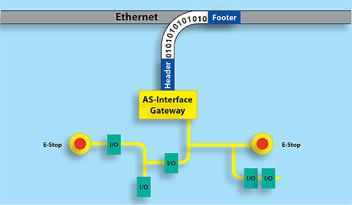
Safety at Work allows safety and conventional I/O to run over the same 2-conductor network. By adding a gateway–in this case EtherNet–a PLC can receive safety diagnostics data and issue reset signals. All safe operations are handled by Safety at Work and not by the PLC. Consequently, a low-cost conventional PLC instead of an expensive safety PLC can be used.
Safety at Work–the past
The Safety at Work technology was developed by a consortium of companies interested in simplifying the transmission of safe data and reducing the complexity of safety installations. AS-Interface, the open multivendor networking and installation technology, was selected as the communication backbone. Reasons for this decision include the following factors:
•It is easy to install.
•It is an established low-level I/O network.
•Over 300 vendors worldwide offer compatible products.
•Safety products can be added to any existing installation irrespective of age.
•The underlying communications mechanism can be easily and inexpensively adapted to transmit safety data.
•The technology can be used with any of the dominant PLCs on the market.
When it was first released to the market in 2001, Safety at Work was based on the simple idea that safety devices like e-stops, light curtains, and door switches are connected to safety coupling modules. These coupling modules in turn transmit data representing the state of the device (such as e-stops released or depressed, protective door open).
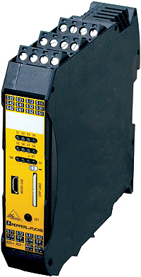
The Safety at Work safety controller is a compact device for stand-alone applications. It also offers the ability to transmit diagnostics data to its AS-Interface expansion port. A modern USB configuration port and a SIM memory card are considered state of the art and simplify usability and maintainability.
Then, the SafetyMonitor evaluates the data. A SafetyMonitor is like a configurable safety relay connected to the network. With these two components, a complete Safety at Work system looks and operates as follows:
•Safe and conventional nonsafe devices are connected to the network.
•Nothing new needs to be learned by installers or users.
•The entire network is powered by an off-the-shelf AS-Interface power supply. Nothing new needs to be learned by installers or users.
Data exchange is controlled by an off-the-shelf AS-Interface “master,” most commonly in the form of a gateway between AS-Interface and any upper-level networking technology like EtherNet/IP, DeviceNet, PROFIBUS, or PROFINET. Note: these gateways are not safety-rated devices and the PLCs receiving their data are conventional nonsafe PLCs; which can be a major advantage in terms of cost. Still, nothing new needs to be learned by installers or users.
•The SafetyMonitor is a safety-rated device on the network. The name “monitor” was chosen because it evaluates the responses that the safety-rated modules send when interrogated by the gateway rather than actively initiating data exchanges with the safe input modules, which is done by the gateway. Because the SafetyMonitor connects like any other AS-Interface device, again, nothing new needs to be learned by installers or users.
•The SafetyMonitor is configured using the graphical SIMON+ configuration tool, allowing any type of setup from simple to complex. This is the first instance where Safety at Work requires the user to do something new.
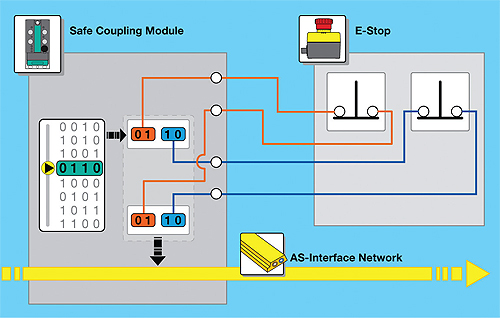
Field-mounted Safety at Work input modules are connected to conventional safety devices, such as an e-stop. It is common practice that Safety at Work safe input modules have two independent test outputs, allowing the quick detection of cross wiring shorts. The PLC receives four bits of data from each safety device representing the two safe e-stop contacts. With these data, it is possible to write simple PLC logic to detect faulty e-stop contacts.
Take a protective door switch, for example. In a Safety at Work installation, the gateway exchanges data with all devices on the network, including the safety module connected to the door switch. When the door is closed, the safety module transmits safety data representing “door closed.” In the case of an open door, it transmits data representing the “door open” state. The gateway, being a non safety-rated device, passes this information on to the nonsafe PLC for diagnostics and annunciation, but is not going to make any kind of safety decision.
Meanwhile, the SafetyMonitor also receives the data from the door. Using that data, the safety configuration determines when and how the safe outputs on the Safety Monitor are activated and deactivated. The safety logic can even contain safe timing, muting, logical AND and OR functions, user acknowledgments, and more. In other words, the SafetyMonitor is primarily a “communication-passive,” listen-only device that receives safety-rated data from the safety-rated input modules. This approach has advantages, including:
•The low-cost AS Interface infrastructure and installation technology reduces setup time while increasing diagnostics capabilities.
•Safety at Work has been approved for PLe (as well as CAT4 and SIL3) without the need to use a costly safety-rated PLC; any conventional PLC can be used to control the machine.
Transmitting safe and conventional nonsafe data over the same network cable adds flexibility while reducing installation complexity. For instance, when an e-stop is activated, the safety module replies with corresponding data. The SafetyMonitor listens to these data and drops out the safety contacts, stopping the potentially harmful operation. At the same time, the PLC–through the gateway–also receives this information and can now activate field indicators (such as turn on the e-stop light, make a stack light blink, or activate a horn) all without having to run or connect a single additional wire.
Since Safety at Work was based on AS-Interface, small safety installations were not always suitable applications. The potential overhead (power supply and gateway) could be too costly for situations requiring only two or three safety devices. Until now, only medium to large systems were suitable.
Safety at Work “stand-alone”
Recently, a new version has been released to the market addressing the need to offer a flexible and compatible system for even the smallest safety applications. It is a Safety at Work controller that offers the following:
•Stand-alone operation using four on-board safe inputs, and two on-board safe outputs.
•Integrated expansion port allowing the system to grow as needed.
Configuration using SIMON+
SIMON+ has a 10+ year history of development and use. Current users of Safety at Work can use the same software tool for all their safety applications. Beginning users, perhaps working on their first small safety system using the stand-alone Safety at Work controller, won’t have to start from scratch if they are faced with growing safety needs.
When used as a stand-alone device, this safety controller is comparable to other “configurable safety relays” on the market. With four safe input channels and two safe outputs, many small applications are easily addressed. This I/O mix was selected because the cost of the product is low enough to be competitive in situations where two or three conventional safety relays may otherwise be used.

Safety logic for the Safety at Work controllers is easily and quickly put together using the graphical SIMON+ tool. Configuration blocks are dragged from the Device Library and dropped on the Configuration Window. Each configuration has a number of parameters that are accessible through its Details Window. Simon+ is used for stand-alone safety controllers and those that come with an integrated gateway to other PLC networks.
One of the main features of this safety controller is the integrated expansion port. This port uses AS-Interface as the communication method between the safety controller and the expansion devices. The Safety at Work approach allows modules to be as close to the controller or as far away from the controller as necessary. Using the expansion port, you can:
•Add up to 32 PLe-rated safety devices.
•Add up to 8 independent PLe-rated safe output channels.
•Connect up to 124 nonsafe inputs and 124 nonsafe outputs.
Now that the Safety at Work technology can be used for installations with as few as two or three safe inputs up to installations with nearly 1000 safe inputs, all configured with the graphical SIMON+ configuration tool, you can inexpensively address your safety needs. Plus, your system can initially be small and grow significantly without throwing away components. The integrated expansion port gives the stand-alone safety controller the ability to handle safety systems of significant size.
The Safety at Work Consortium
The AS-Interface Safety at Work Consortium was founded in 1999 to develop the economic advantages of using the AS-Interface cabling for safety-related components. The objectives of the consortium are to assist the marketplace and the technological development of the Safety at Work system. The transmission reliability of the AS-Interface, even under critical environmental conditions, makes it possible to integrate safety components using the Safety at Work technology. Complex parallel wiring of safety components has been replaced by the Safety at Work system and integrated into the existing AS-Interface system.
This means it is now possible to implement wiring of safety components with the AS-Interface in addition to the sensor/actuator cabling.
To enhance the potential of the standard (EN 50295 and IEC 62026-2) AS-Interface system, development work ensures that the Safety at Work technology is easy to integrate into existing AS-Interface systems. TÜV and BIA approvals were granted in May of 2000.
Pepperl+Fuchs
www.pepperl-fuchs.us
::Design World::
Filed Under: Factory automation, CONNECTIVITY • fieldbuses • networks, INDUSTRIAL SAFETY SYSTEMS, Motion control • motor controls, PLCs + PACs


Tell Us What You Think!