Composite materials, and particularly fiber-reinforced composites, present an interesting challenge. They have superior properties, compared to homogeneous materials, and have the potential to help engineers and designers meet increasingly challenging product requirements. Yet, they can be maddeningly difficult to engineer properly.
To understand why this is so, you need to look closely, at the structure of composites.
A composite is a combination of two or more component materials, which, acting together, provide properties significantly different from either of the materials alone. The first type of material is a bulk phase, in the form of a continuous solid—often metal, ceramic, or polymer. The bulk phase provides the overall shape and structure of the composite. It is also commonly referred to as the continuous phase, or matrix. The second and subsequent types of material are dispersed, non-continuous, phases—often particles, flakes, or fibers. These are also variously referred to as discrete phases, inclusions, fillers, or, most commonly in the context of structural composites, reinforcements. The region where the discrete phases meet the matrix is called the interface.
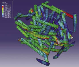
FEA simulation of stress contours in fiber reinforcement of a composite.
The term “phase,” in the context of materials science, means a material having a distinct combination of physical properties. In most cases, different phases are just different materials, but different phases can also be the same material with a different structure.
It’s possible to create composites optimized for a variety of properties, including electrical, thermal, optical, electrochemical and catalytic. For mechanical engineers, designers, and analysts, the composites of most interest are often those optimized for mechanical properties such as strength, weight, rigidity, toughness, and durability. In composites of this type, a relatively ductile matrix accepts the load over a large surface area, and transfers it to the stronger, and more brittle, reinforcement.
Mechanical properties
The mechanical properties of a composite material are strongly related of the properties of its constituent phases, and its microstructure. Differences in the volume, size, shape, and orientation of the reinforcement affect its coupling with the matrix, and can make dramatic differences in the macroscopic properties of the composite.
It’s possible to predict the mechanical properties of a composite using the techniques of continuum mechanics. The process, called homogenization, starts with the properties of the constituent phases, and a microstructure model for a representative volume element of the composite (often created using statistical methods.)

Percolation study of a Polymer/CNT Nanocomposite Representative Volume Element
There are quite a number of analytical and numerical approaches to homogenization. The applicability of different methods is a subject best left to materials scientists, but the rule of TANSTAAFL (there ain’t no such thing as a free lunch) seems to apply. Faster methods tend to use simplifying assumptions. More accurate methods tend to be more computationally expensive.
How it’s made matters
In practice, the microstructure of a composite material is strongly affected by the manufacturing processes used to turn it into a part. With many of the most interesting composite materials, it can be challenging to get an optimal microstructure throughout the entire part.
Carbon fiber laminates provide a good example of this. Carbon fiber itself is uniaxial, having very high mechanical properties along its longitudinal axis. When combined with a matrix and manufactured as a laminate, it can become orthotropic, quasi-orthotropic, or anisotropic, depending on how it is layed-up and loaded. Applying a load to an unsymmetrically laminated plate causes coupling between extension, shear, bending, and twisting, and results in unusual deformations. Manufacturing variations, such as voids and relatively small variations in fiber alignment (especially common with complex curved surfaces) can degrade the mechanical properties of the composite in difficult to predict ways.
Discontinuous glass fiber reinforced thermoplastic components are also challenging to manufacture. The shear inherent in the injection molding process is hard on the brittle fibers, and tends to break them, distort their distribution, and alter their alignment. This results in differences in volume fractions and fiber orientations throughout the volume of the part. As you might extrapolate, it also results in differences in mechanical properties throughout the volume of the part. Longer fibers are more susceptible to this. They’re also more sensitive to geometric challenges in the mold, such as thin walls and welds.

Thermal conductivity model of a CNT Nanocomposite Representative Volume Element
A good example of the challenge posed by fiber orientation can be found with the ISO 527 standard for determining tensile properties of plastics and plastic composites. The standard specifies a process for creating and testing material specimens—yet, when used with non-continuous fiber reinforced materials, there seems to be no way to be certain that the specimens will have a particular fiber orientation (especially the orientations that would be most useful to know, such as longitudinal, transverse, and random orientations relative to the applied loading.) The material properties calculated based on this testing may over- or under-predict what you can expect with your own parts.
Because composites do not perform as predictably as homogenous materials, many manufacturers qualify them through extensive physical testing of prototypes. In instances where there are significant process-induced material properties, the level of physical testing required to understand how a composite part will perform under real-world conditions might be so expensive and time-consuming as to be impractical. Beyond this, without accurate material properties, designers cannot optimize the design of the composite part, and must resort to over-designing—which defeats the purpose of designing with composites.
The best solution to this problem is to combine physical testing with simulation.
The first approximation
The standard approach to the simulation of laminated composites is to start from the beginning with specialty software, such as ANSYS Composite PrepPost, Siemens PLM FiberSim, or Autodesk Helius:Composite Pro.
But, with fiber reinforced molded composites, there is no such specialty software. The most common starting point for simulating these kind of parts is to use a standard FEA program, and make a simplifying assumption that the material is isotropic. This allows you to use a single value for the Young’s modulus. During the early design phase of a project, this approximation is better than nothing. Whether it is good enough, or completely misleading, depends in part on whether the value you choose is reasonable.
The problem is to know what a reasonable value is. There are a few approaches to this: Use the value provided by the resin supplier, use a knock-down factor, run some material tests to calculate an equivalent isotropic value, or find a material scientist and ask them.

Von Mises stress contour of a long continuous fiber composite
No matter what Young’s modulus value you might use for a first approximation simulation, it’s important to remember that it won’t be 100% accurate. This is because the mechanical properties of the part are not likely to be uniform throughout the part.
A good way to begin to understand the process-induced properties of these components is to run an injection molding simulation, using software that will calculate fiber orientations and other distribution characteristics. Autodesk Moldflow, Moldex3D, and several other molding simulation programs have this capability, but may require additional software to transfer this information to an FEA solver.
The approach of coupling molding simulation with FEA provides good results, but is limited to static linear-elastic analyses. It doesn’t account for non-linear material properties, and so cannot be used for transient analysis, eigenfrequency analysis, or to predict ultimate strength.
The state of the art in the simulation of composites is multiscale modeling, where macrostructure analysis (FEA) is coupled to microstructure modeling, to calculate local material properties. This approach can support multiple material models (including nonlinear materials, elastic, elastoplastic, viscoelastic, and thermoelastic), and nearly any form of multi-physics simulation. The best known tool for microstructure modeling of multiphase composites is Digimat, from the e-Xstream Engineering division of MSC Software.

FEA with Digimat material models reveals a lower maximum displacement when compared to a conservative isotropic material representation.
How much simulation do you need?
If you’re using composites in your products, there are probably some good reasons why, such as weight or strength. It’s too much trouble and too much expense to do poorly.
While it’s possible to do first approximation (isotropic) or second approximation (linear anisotropic) simulations, these are not really good enough to predict the real world behavior of composite components. The only reliable way to simulate composite components is through multiscale modeling. It does require a couple of steps past isotropic assumptions, but it’s the cost of entry to do composites right.
ANSYS
www.ansys.com
Siemens PLM
www.plm.automation.siemens.com
Autodesk
www.autodesk.com
Moldex3D
www.moldex3d.com
MSC Software
www.mscsoftware.com
Filed Under: Software • 3D CAD, Software • CAM

I need a huge help…
Am making an analysis of composite materials which is a combination of natural reinforced fibers. Like kenaf,sisal..and using resins as a binder… and analysing with Ansys workbench 16.2
The major doubt is that…
How can i model those composite with all the natural fiber and resin!
And how could i analyse them!
**am waiting for the reply.. as soon a as possible. . Its my humble request to make me some ideas!
Thank you.
Thank you for this informative article. I would like to ask could you please share the fibers random distribution model/script which you have shown in fig.1 to fig.3? I have searched alot but I can not figure out how to model random fiber distribution in Ansys WB. The RVE model which you have shown here seems to fulfill my requirements.
Hope to hearing from you soon.
Hey Dinesh did you find any information? I have a similar project to make natural fibre reinforced composites (short and discontinuous). Any idea on how to model this?
Hi Rishi Dam did you find any information? I have a similar project to make natural fibre reinforced Brick. Any idea on how to model this?