By Gregory Herman
Gregory Herman, Enidine, Inc., ITT Energy Absorption
One of the most critical parameters that machine builders have to deal with is changing the speed of moving members and components. Accelerating and decelerating loads in a prescribed time is essential for operator safety as well as economy and efficiency of motion to optimize the machines’ output. Often, machine parts move at extremely high speeds and must be decelerated or stopped without damaging the machine or its payload.
Brakes and clutches fit well with motors and transmissions for controlling rotary motion, but shock absorbers are better suited for stopping components moving along a linear path. For example, shock absorbers are designed into specialty machinery used for automotive and furniture manufacturing, packaging, lumber processing, and numerous other industries. The procedure for selecting a shock absorber is relatively easy, but a few time-proven guidelines can help ensure a robust, effective, and safe system.
Physics review
The law of Conservation of Energy states that energy can neither be created nor destroyed, but it can be converted from one form to another. Two primary forms of energy considered for shock absorbers are kinetic energy (mass in motion) and thermal energy (heat). Hydraulic shock absorbers or hydraulic dampers convert the kinetic energy to thermal energy while decelerating a load.
The six steps
Step 1:
The first step in selecting a shock absorber is to gather all of the required information to size the shock absorber properly. This information typically includes the weight and velocity of the moving mass and the anticipated number of cycles it undergoes in an hour. First, determine the amount of kinetic energy (EK) in the system.
EK = W/(722)(V2)
Where:
EK = kinetic energy, in.-lbs
W = weight of moving mass, lbs.
V = velocity of moving mass, in./s
This equation represents the amount of kinetic energy that the shock absorber will convert to thermal energy each time it is impacted.
Step 2:
Calculate the work energy in the application. Work energy (EW) is defined as the amount of energy a motor or other device generates to move the load:
Ew=FD x S
Where:
Ew = work or drive energy, in.-lb
FD = force output of the motor (drive force), lb
S = stroke of the shock absorber, in.
Then the Total Energy (ET) in the application per cycle (in.-lb/C) is:
ET=EK + EW
If more than one shock absorber is used, the total energy (calculated above) divided by the number of shocks determines the total energy per shock. If a single shock absorber exceeds its rating to convert kinetic energy to thermal energy, the shock’s temperature rise may exceed its capacity and critical internal components could fail such as hydraulic seals.

Industrial shock absorbers contain one or more orifices and metering pins. The damping force varies in proportion to the square of the piston velocity and can be designed to be either dependent upon or independent of the stroke position.
Step 3:
Determine the total energy ET that the shock must convert in one hour.
Multiply the ET by the total number of cycles per hour C:
ETC = ET x C.
Where:
C = repetition rate, cycles/hr.
Step 4:
Determine the shock force, Fp (lb). Shock force is defined as the resistive force required by the shock absorber to stop the moving load:
Fp =ET/(S x.85)
Where:
S = the stroke of the shock absorber (85% efficiency), in.
This is a critical component for selecting the appropriate shock absorber because the machine must have sufficient strength to support the shock absorber as it resists the shock force.

Shock absorbers have controlled and predictable deceleration. The moving piston pressurizes the fluid and forces it through the orifices, which heats the fluid rapidly. The heat conducts to the cylinder body and then to the atmosphere. Increasing the impact weight (from curve 1 or W1 to curve 2 or W2, with the velocity unchanged) increases the damping force at the end of the stroke
and the force transfers to the mounting structure and impacting load.
Various forms of damping can be used, each of which depends on the application. The differences in these damping characteristics relate to the efficiency of the damping used. The efficiency is measured by evaluating how much of the stroke of the shock is used in the actual damping of the motion. Shock absorber efficiency increases as more energy spreads over the stroke of each one. The more efficient shock absorbers typically yield the lowest shock forces when the stroke of the shocks is equal.

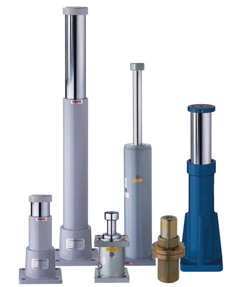
Enidine heavy-duty, large-bore hydraulic shock absorbers protect equipment from large impacts in various applications such as in automated storage and retrieval systems, overhead bridges, and trolley cranes.
The graph illustrates two different shock curves. The amount of energy absorbed in both cases is identical. However, curve number 1 uses the highest percentage of available stroke to absorb the energy and is the most efficient. Curve number 1 also occupies the lowest point on the curve, which is the minimum shock force and may be the most desirable.
Selecting between the various damping configurations depends on the application. Parameters such as velocity, cycle rate, and fragility of the machine or payload typically determine which one is the best fit. In addition, some applications may have a specified g-load rating to protect the load being moved. For example, a large overhead crane may also house the operator, and he must be protected from excessive g-forces.
Step 5:
Calculate this g-load:
g = (FP – FD)/W
Step 6:
When all calculations are complete, a shock absorber can be selected that meets all of the application’s requirements. Make certain that it meets all of the requirements simultaneously;
otherwise it can fail prematurely. For example, if the selected shock absorber meets the energy per cycle requirement, but not the energy per hour requirement, it will surely fail too soon.
Enidine, Inc.
www.enidine.com
:: Design World ::
Filed Under: Automotive, MECHANICAL POWER TRANSMISSION, Shocks + vibration control • gas springs


Where does the constant of 722 come from in the kinetic energy equation? Why don’t you simply use 1/2 mv^2? I am sure there is a step between the typical KE formula and the one shown, but I’d like to know what it is.
Where does the constant of 722 come from in the kinetic energy equation? Why don’t you simply use 1/2 mv^2? I am sure there is a step between the typical KE formula and the one shown, but I’d like to know what it is.
They just converted the value of g into in/s^2 and multiplied that with 2,
and also
W = m*g
m=W/g
g = 386 in/s^2
you can just Put these Values in Equation.