By Brien Shirey, VP of Engineering, CGI, Inc. Carson City, Nev.
Considering the need for a gearhead early in the design stage of a motion application will save time and effort (and headaches) further down the road.
When designing a motor into a motion control system, all too often the benefits of a gearhead are realized much too late. Designing in a gearhead at the end of the project will many times cause delay and additional cost, which could have been prevented if it had been considered at the start of the project. Understanding all of the advantages that a gearhead provides can help you design a successful motion control project.

Planetary gearheads are available in a wide array of configurations shown here, including shaftless and shafts of differing lengths and styles, as well as right –angle gearhead assemblies.
Consider these six tips to help you select the proper planetary gearhead for your motion control application.
1) Consider a gearhead early in the project
All too often, when designing a motor into a motion control system, cost is generally the driving factor that influences the design. In keeping what is thought to be auxiliary components to a minimum, a gearhead is often disregarded in hopes that the motor itself can handle the application. However, in many cases, the necessity of a gearhead is understood when the use of the motor (alone) then presents challenges, and it is usually at about the time the project is due to ship to the customer. After the initial design oversight, a gearhead is then determined to be required and it usually needs to be applied into a space that originally was never intended to accommodate a gearhead. In short, the cost of redesigning a motion application to incorporate a gearhead afterwards will usually prove more expensive than if it was designed in from the start. In particular, planetary gearheads have some distinct benefits in motion control applications. They can offer improvements in system response, inertia matching, speed matching, system stiffness, and system resolution.
2) System response
System response and inertia matching are particularly important because sometimes the application inertia can be several times greater than the inertia of the motor, which can then result in a sluggish and disappointing motion reaction. When you integrate a gearhead into the system, it decreases the reflected load inertia at the motor shaft by the inverse of the square of the gearhead ratio. What that really means is that a gearhead can make a motor act as if it is magnitudes larger than it really is, and then it handles the load with power to spare. The ideal situation is to have the motor rotor inertia equal to the application load inertia (or as close as possible), which will result in snappy system response, which is exactly what a gearhead can do.
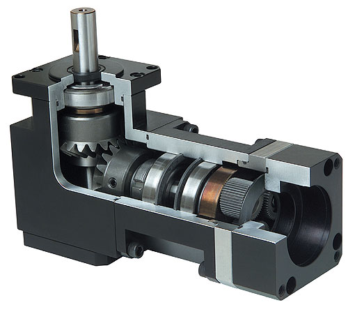
A cutaway view shows the inner workings of a right angle planetary gearhead assembly.
3) Speed matching
Besides giving a motor muscle, a gearhead can also offer the performance advantage of speed matching. Most electric motors have an optimum speed (rated RPM) that they were designed to run at most efficiently. With the use of a gearhead, you can achieve two separate, favorable speeds; a speed that is optimum for the motor and a speed (resulting from the gearhead ratio) that is optimum for the application. When initially considered as part of the motion design, speed matching can produce greater component longevity for the application.
4) System stiffness
When a motion system lacks stiffness, a number of unanticipated problems can arise. Issues can include system compliance, wind-up, harmonics (ringing), unpredictability, premature wear and system vibrations. This is where a gearhead can alleviate many issues. The addition of a gearhead onto a motor can increase the motion system rigidity or stiffness in direct proportion to the gearhead ratio. Forces such as load variance or back-driving (reflected) loads then become more easily managed with the use of a gearhead. The result will typically be a more reliable and precise system control that eliminates these issues.
5) Resolution
In addition to system improvements like swift response, greater power, extended longevity and maximum stiffness, a planetary gearhead can benefit system resolution. The better the system resolution is, the more precise the control of movement becomes. For example, a 10:1 ratio gearhead coupled with a motor will magnify the motor’s positioning ability, resulting in more precise movements and better accuracy at the application by a factor of 10. Motor cogging or step size (when using a stepper motor) is also directly reduced by the gearhead ratio, providing a more consistent and smooth motion response.
6) Know your application
Among the most important items of information an engineer needs to firmly possess when evaluating the application is an acute awareness of the motion profile and load requirements. Additionally, understanding system elements such as torque profile, overhung loading, system stiffness, sensitivity to backlash, duty cycle, environmental concerns, life expectancy and shock loading is necessary for the success of a gearhead in a motion application. The more application requirements that are known up front, the easier it is to prioritize and balance what is needed when choosing the optimum gearhead size, configuration and ratio. For example, a ratio that optimizes speed matching may not work well with the target inertia matching in some applications, so knowing the priorities and demands of a motion application is key. It becomes a juggling act when trying to achieve all of your priorities when designing a motion system. However, the benefits of using a gearhead will help find the right balance in meeting applications objectives.

Also, when selecting a gearhead supplier, you should consider the engineering and sales support teams as well as building a long-term support relationship. On-time delivery is another critical factor in meeting custom requests for both small and large quantities. Last but not least, look at the engineering and manufacturing processes the company employs. This could include 3Dmodeling, FE analysis, CAD/CAM, scanning CMM technology and an all-inclusive ERP inventory management system.
Discuss this on The Engineering Exchange:

CGI, Inc.
www.cgimotion.com
Filed Under: TEST & MEASUREMENT

Tell Us What You Think!