By Tom England, Director, Global Product Planning, Kollmorgen Radford, Va.
Improving servo system design can dramatically improve the quality of products in coating and laminating applications.
Coating and laminating applications are some of the most demanding for extremely precise speed regulation. The biggest challenge is avoiding velocity ripple which causes uneven coating and undesirable horizontal bars across the substrate.
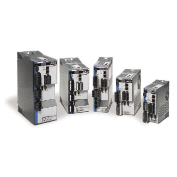
Kollmorgen’s Ethernet-based AKD servo drives are fast and easy to integrate into applications and offer features such as plug-and-play commissioning.
The key to achieving the most uniform coating is minimizing variations in velocity as well as in metering of the coating material. Mechanical transmissions such as gearboxes and timing belts can cause torque perturbations resulting in imperfections in the coating.
Coating and Lamination Loads
Coating and laminating applications are characterized by compliance caused by the elasticity of the web, which in turn produces variations in torque requirements. The coating or laminating process typically generates a fairly steady level of frictional force. The roll itself, and its bearings and shaft extensions, are usually large in comparison to the drive motor, which generally creates an inertia mismatch.
Web handling machines face the challenge of handling these loads while avoiding velocity ripple that can cause uneven coating and unsightly horizontal bars across the substrate. As an example, consider film coating, where depositing a dark film onto the substrate material at varying velocity would result in a series of dark and light “bars” across the material. As web speed and quality requirements have increased, the inevitable inaccuracies in the mechanical transmission and servo system have become the limiting factor on coating and laminating uniformity.
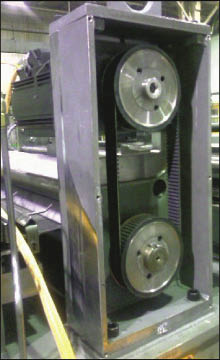
An example of a press-feed machine built with a conventional servomotor, gearhead, and belt and pulleys.
Mechanical transmissions can have a negative impact on coating and laminating quality by causing tooth or belt chatter. Backlash is inevitable in any mechanical transmission system. Transmission components such as lead screws, gearboxes, and belts and pulleys all contribute error between the motor and the load. Even when a geared system is tuned tightly, the gears will wear and backlash will begin within a short period of time. Backlash causes the roller and cylinder to rapidly accelerate and decelerate as the gear teeth bounce back and forth against each other. This causes uneven coating of the substrate made obvious by the appearance of alternating light and dark horizontal lines on the product.
Direct Drive Systems
There are several things designers can do to minimize these problems. Using direct drive systems is one way to improve coating and laminating quality and uniformity. The most important is the motor, but the feedback device and the servo drive are also critical. DDR (Direct Drive Rotary) motors with reduced electromagnetic cogging combined with high performance digital servo drives using versatile filters can isolate resonances and mechanical disturbances and provide high bandwidth control of the roll.
In some cases, such concerns can be adequately addressed by selecting high-quality mechanical transmission components. However, components can be expensive and they are ultimately subject to wear. An alternative is to consider a DDR system which eliminates the transmission altogether. In direct-drive systems, the motor directly drives the load. The accuracy of direct-drive systems can be up to 60 times better than that of traditional systems and audible noise can fall by 20 dB. Other measures such as servo response (or bandwidth), machine parts reduction, and reliability can also dramatically improve.
When the load is directly coupled, there is no limitation on the inertia mismatch between load and motor. The servo loop gains can be increased significantly to boost servo stiffness and achieve excellent speed regulation to optimize product quality. A benefit is that web speeds can be increased in many applications using direct-drive technology because the accuracy of the mechanical transmission system is often the limiting factor.
Eliminating transmission components such as gearboxes, belts, rack and pinion, and pulleys eliminates compliance, backlash, and component wear. The accuracy increases, inertia-matching requirements relax, acceleration and deceleration improve, maintenance becomes minimal, and the product life increases by a significant degree.
DDR motor size is based on the peak torque required for the desired acceleration time specifications. With direct drives, inertia mismatch of 250:1 is common and mismatch of 800:1 is not uncommon. In many coating and laminating applications, the size of the motor is dictated by the inertial matching requirements. The result is that a much smaller and more energy-efficient DDR motor can be used in most applications.
The motor’s primary contribution to velocity ripple is its electromagnetic cogging, which is usually at the pole or slot frequency or some multiple of it. The best way to overcome electromagnetic cogging is to begin with a low cogging motor that requires less correction. High-performance motors with less than 1% pk-pk cogging are a good start, and nearly always superior compared with standard motor options due to better electromagnetic design and simulation of the electromagnetic circuit.
Frameless Direct-Drive Motors
The first frameless direct-drive motors were designed into the machine architecture along with a feedback device and became a fully integrated part of the machine. This approach had the advantage of consuming the least amount of space. On the other hand, frameless motors are relatively expensive to fully integrate as they typically require substantial changes to the design of the underlying machine. Frameless motors are also more difficult to service because they are embedded into the machine. While the initial development cost may be high, the benefits of higher performance, higher quality, and small space requirements usually justify this technology in some applications.
The next generation of DDR technology, sometimes referred to as full frame systems, integrates all of the components of a complete motor including the rotor, stator, bearings and feedback device within a housing. The machine shaft slips through the bore in the motor and attaches to the rotor. This approach substantially reduces development costs since the motor no longer needs to be integrated with the coating roll. The disadvantage of this approach is that the motor and machine bearings must be precisely aligned, which is a complex and time-consuming task. The bearings in the motor and the load are directly coupled linearly, making it nearly impossible to align the system components properly without causing premature bearing failure due to uneven loading.
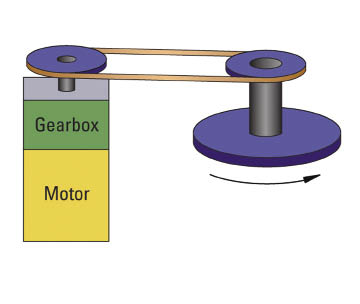
A traditional servomotor and gearhead mechanical transmission system can cause torque disturbances from tooth or belt chatter, leading to imperfections in coating and laminating quality.
The most recent approach to DDR systems is the Kollmorgen Cartridge DDR servomotor which is fully housed and ready for mounting to the machine. However, it has no bearings in the motor, but instead uses the host machine to support the motor’s rotor. This approach makes it easy to use direct-drive technology on machinery that already has bearings, particularly in applications such as coating, laminating and printing where rollers already use heavy-duty, precision bearings. The motor has a hole in the middle which slips over the shaft extension of the roll and the motor housing bolts to the machine frame.
Effects of Feedback and Servo Drives
In addition to the motor, the feedback device and servo drive are also a critical part of the overall system. Because the feedback device is in the control loop, any error of the device itself is corrected by the drive in the servo loop, and ends up as a velocity ripple on the coating roll. As the servo loop gain is increased, the error in the feedback device is amplified and transferred into the coating roll. So, starting with as precise a feedback device as possible is important to minimize velocity ripple. There are several ways that accuracy can be improved. The most straightforward is to use a more accurate device. For example, most encoder manufacturers offer encoders in a variety of resolutions. Resolution is usually measured in lines per revolution. Encoders with higher line counts usually have greater accuracy. However, this is not always the case, so users must check the specifications of the encoder carefully. In some cases, highly resolved devices can still be relatively inaccurate.
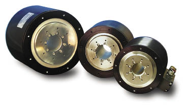
Housed direct-drive rotary (DDR) series motors from Kollmorgen combine large diameter, short length and a high number of magnetic poles to boost torque density, and eliminating the need for transmission components such as gearboxes and timing belts.
Users can also change the type of feedback device. Sine encoders are the most accurate motor-mounted feedback devices commonly used in industrial servo systems. Sine encoders are typically accurate to ±25 arc-sec, compared with a resolver at +/- 10 arc-min. High-line-count incremental encoders (above 10,000 lines-per-revolution) are also often highly accurate. Medium line-count encoders (2,000 to 10,000 lines-per-revolution) are fairly accurate, usually holding 3 arc-minutes or less. Resolvers are the least accurate sensors, typically holding from 5 to 20 arc minutes.
The drive can also add to and correct various velocity ripple components. It adds to the ripple by having uneven current loop gains in each of the phases, i.e. phase A might be 1% higher than phase B or C and this causes a torque error in the motor. Likewise, the amplitudes of each phase might be slightly different, adding an error to the torque as well. The drive can correct these by having digital adjustments in the current loops to take out these offset errors.
Velocity ripple can also be reduced by using harmonic correction in the current waveform. For example, when the characteristic of the cogging in the motor (frequency and amplitude) is known, this can be corrected by applying an anti-phase ripple in the 3-phase current from the drive. The same can be done with the feedback device to correct a repeatable error. Both the motor and feedback error frequencies are well known and repeatable, so all that’s left to do is adjust phase and amplitude.
Low inertia construction is inherent to the design of most permanent magnet servomotors. This means that mismatches between the high inertial loads of the roll and the low loads of the motor need to be accounted for. Servomotor control systems can be tuned to handle inertia mismatches that are inherent in coating and laminating applications. But the gain in the servo amplifiers needs to be optimized to maximize response while avoiding instability and oscillations.
The traditional approach to compensate for inertial mismatches and compliant loads is to use low-pass, band-pass and high-pass filters to eliminate the unwanted frequencies. The problem is that the multiple filters required to eliminate the resonances introduce calculation delays and phase shifts which have a tendency to throw the system out of control.
Recently, there have been substantial improvements in performance with the use of bi-quadratic filters that can emulate nearly any combination of simpler filters without introducing significant delays. The bi-quad filter tunes out problematic frequencies, making it possible to optimize servo system performance. For example, if the mechanical system has a 200 Hz resonance, the bi-quad filter can be configured to remove 200 Hz while providing high levels of gain and bandwidth.
Kollmorgen
www.kollmorgen.com
Filed Under: Factory automation, Motion control • motor controls, Motors • servo


Tell Us What You Think!