By Murad Abu-Khalaf, Rong Chen & Arkadiy Turevskiy, The Mathworks, Inc., Natick, Mass.
Tuning a PID (proportional-integral-derivative) controller appears easy, requiring you to set just three gain values; a proportional, integral, and derivative gain. In fact, safely and systematically finding the perfect set of gain values for a control system can be a complex task. Traditionally, PID controllers are tuned either manually or using rule-based methods. Manual methods can be iterative and time-consuming. Rule-based methods also have some limitations; for instance, they do not support certain types of plant models, such as unstable plants and higher-order plants. In addition to tuning, PID control involves design and implementation challenges, such as discrete-time implementation and fixed-point scaling.
However, the Simulink software suite of tools simplifies and improves the design and implementation of PID controllers. It saves time and development cost and can quickly and easily move designers from the concept stage to code that can be downloaded to a microcontroller to control a physical device or system.
The four-bar linkage system: a design example
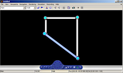
Figure 1: A four-bar linkage mechanism with the stationary lower link shown in blue.
As an example, consider a four-bar link. A four-bar link is a multi-lever device that’s used to convert rotary motion to reciprocating motion. Such links are used in a wide range of applications, including car suspensions, robot actuators and aircraft landing gears.
The control system for the four-bar linkage system has two elements; a feedforward controller and a feedback PID controller. Feedforward control inverts plant dynamics; it handles the major motion of the mechanism by taking into account the nonlinear behavior. Feedback PID control keeps positioning errors small in the face of modeling uncertainties and external disturbances.
The PID controller takes the error signal between the desired and actual rotation angle of one of the links and creates a torque request. This request is added to the torque request from the feedforward controller, and the sum signal is used to drive a DC motor that actuates rotation of the joint connecting the links. The controller must stabilize the operation of the plant. It must also minimize the response time and the amount of overshoot in the system. Because the controller will be implemented on a 16-bit fixed-point processor, it needs to be in discrete-time form, and the gains and calculated signals must be scaled accordingly.

Figure 2: The control architecture for the four-bar linkage system.
The plant model consists of a four-bar linkage mechanism and a DC motor. The controller architecture, shown in Figure 2, is a discrete-time PID controller block that is pulled from a standard control library. With the plant and control system configured, the controller can now be tuned. Tuning the controller is as simple as opening a PID controller block dialog box, specifying a controller sampling time, and clicking a button to open a PID tuner graphical user interface (GUI). Before displaying the GUI, the software linearizes the plant at the current operating point and derives the linear time invariant (LTI) plant model seen by the PID controller block in the feedback control loop. The software also takes into account any computational delay associated with sampling. Using an automatic tuning method, the software then generates an initial set of gains for the PID controller. This tuning method imposes no limits on plant order or time delay, and it works in both continuous and discrete time domains.

Figure 3: C-code implementation of the 16-bit, fixed-point PID controller. The code is generated from the PID controller block.
You can then see an initial setpoint tracking response of the closed-loop system using the initial set of gains for the PID controller generated by the software. If the controller performance meets design specifications, pressing “Apply” updates the values of P, I, D, and N gains in the PID controller block dialog. The system performance can then be tested by simulating the nonlinear model and looking at the results. Another option in the GUI allows for controller tuning interactively using a simple slider to make the controller faster or slower.
To implement the controller on a 16-bit microprocessor, the control design must be scaled for the fixed-point arithmetic supported by the particular controller chip. This is done through a GUI in the software that applies the settings required for a fixed-point design automatically. The next step is to run a simulation using fixed-point settings to verify that the fixed-point design results closely match the results obtained when the controller gains and signals were implemented as double-precision values.

Figure 4: Simulation results comparing the performance of the generated C code with the performance of the double-precision PID Controller block.
With the PID controller prepared for implementation, the final step is to generate the C code. To test this code, replace the PID controller block with the generated C code and run the code in closed-loop simulation. The simulation can now be run using the C code that will run on the actual processor. Simulation shows that the generated code produces results that closely match the results obtained with the PID controller block with double-precision values. This code can now be deployed to the microprocessor to begin controlling the four-bar linkage system in real time.
Discuss this on the Engineering Exchange:

The Mathworks
www.mathworks.com
For more information on the suite of Simulink controller design tools, and to view a demo of an Automated Tuning of a Simulink PID Controller block, visit www.mathworks.com/pid-tuner.
To view a demo on designing a Simulink PID Controller Block with 2 degrees of freedom for a reactor, visit www.mathworks.com/pid-controller.
Filed Under: ENGINEERING SOFTWARE, Motion control • motor controls


Tell Us What You Think!