By Detlef Stork – Technology Manager, Motion – Lenze

Lenze drive and motion-control systems integrate robots with software using standardized modules represented by the boxed sketches here. The Feasibly Applicable Software Toolbox (FAST) modules use standardized interfaces that combine in myriad ways, even with a designer’s own software. Functions are scalable to meet the requirements of the task in hand.
Machine builders must deliver designs with more flexibility than ever. Standardized motion software helps them go beyond segregated component and drive purchases with efficient programming of even complex robotic movement.
Today’s increasingly custom products are leading to smaller production batches, so production machinery is becoming more flexible. Robots are useful here because they’re not tied to rigid motion sequences. No wonder robots are on the rise in industrial manufacturing, especially in the packaging industry. The only catch is that it can be difficult to integrate robots (and their controls and kinematics) into larger automation systems. It’s still standard practice for machine builders to buy kinematic axes and program them from scratch, or to buy proprietary turnkey robots and add them after the fact. For the latter, builders must integrate the robot control with consistently compatible software and communications. In contrast, builders that use free kinematics must do copious programming.
How does modular software for motion work?
No matter a machine’s kinematics, the aim is always to produce motion in a multi-dimensional space—either by linear interrelationships (as in a gantry) or nonlinear moves (as from a delta robot). The application dictates which is suitable.
Especially for Cartesian robotics, some manufacturers now offer software toolboxes with standardized and reusable software modules to let machine builders set up flexible robot stations more easily. They let builders treat machinery controls and motion functions holistically. The modules adhere to the technical specifications of PLCopen and IEC 61131-3 and include complementary functions for delta-robot controls, electronic camming, conveying, cutting and tensioning.
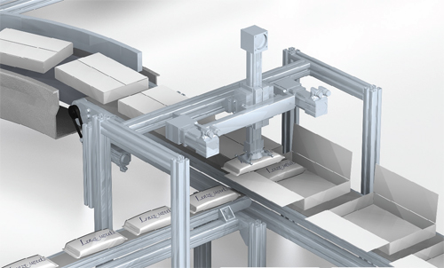
Shown here is one setup that’s possible with Lenze’s FAST software. It is function-building-block software that lets machine designers virtually assemble predesigned control modules. The software includes interfaces for camera systems that detect objects for the robot to handle.
Once a designer picks a general kinematics model, the software runs on automation equipment (including drives and motion controls) from one manufacturer. So, on the hardware side, motion and robot control (traditionally separate) become one. That simplifies physical setup and programming so designers can focus on what specific robotic movements should look like.
In the years to come, such hardware and software innovation will put robots in jobs currently done by specialized machines. In fact, modular software can already set multi-axis kinematics to automate tasks too big for standard robots. Machine flexibility reduces efforts in mechanics, electrical engineering and programming … so small- and medium-sized machine builders can integrate robot kinematics into designs with kinematics tailored to the task at hand.
Breaking tasks down into motion constituents
Consider technology modules for pick-and-place motion functions and corresponding coordinate-transformation functions for alternative kinematics (read: delta or Cartesian robots) based on PLCopen Part 4. The designer sets hardware parameters to define motion functions—including the coordinate system, material speeds and acceleration, radii, and rounding. Then the kinematics model parameterizes the mechanical variables such as arm lengths and distances between parallel struts. In this way, designers can reference, traverse and commission a robot-automation cell without programming.

Lenze’s FAST software speeds the implementation, so machine builders can quickly assemble software for complete production lines like this one.
Currently, there are kinematics modules for gantries, belt kinematics, articulated robots, SCARA robots, and two- and three-axis delta robots. Elements for all their tasks are in the technology and kinematics modules. So now, engineers only need to know what a motion task should look like and not how to program a robot to make those moves. What’s more, if the design team needs to add another kinematics system, they only need to mechanically integrate the design, replace the corresponding kinematics model and set the necessary mechanical parameters.
Some software also has application templates (some quite specific) to implement modularized tasks in the controls. For example, OMAC versions of one template let packaging-machine builders implement applications in accordance with the PackML standard. The template accepts custom program components just as easily as technology modules.
As mentioned, some modules let designers implement robotics through simple parameterization instead of programming a controller. Once the controller takes control of the other axes of the machine system and process, programming complex interfaces is unnecessary.
In fact, motion-component manufacturers have offered application software for years with dedicated winding, cross-cutting, conveying, separating, grouping or sealing modules. Only recently have some added robotics applications based on PLCopen Part 4 … including those for pick-and-place moves through alternative kinematics … with other modules for more machine applications on the horizon.

Lenze’s FAST software speed implementation so machines builders can more quickly assemble software for complete production lines like this one.
Software modules for machines, too
Standard hardware and software also support modularization of machines. Here, builders can use software to break down the complexity of tasks into parts. Then, standardized technology modules let builders create and reuse designs for less engineering to get to machine production. That boosts software quality, so there’s less need for testing as well. Ultimately, the standardized and reusable modules free programmers to concentrate on developing and testing special machine functionalities that give designs unique features to benefit end users.
Lenze
www.lenze.com
Filed Under: The Robot Report, ENGINEERING SOFTWARE, MOTION CONTROL


Tell Us What You Think!