By Hermann Bestle, Mechanical Engineer, Mayr GmbH, Mauerstetten, Germany
Electromagnetic safety brakes help reduce energy requirements, produce little heat and feature extremely short switching times.
Safety brakes are critical components in many types of industrial applications, including machine tools and motion control systems. Electromagnetic safety brakes ensure reliable and safe braking of machines and systems in any position in the event of a power switch-off, a power failure or an emergency stop.
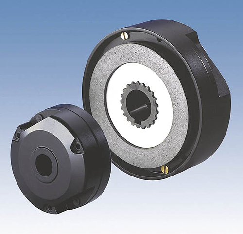
Optimum control of safety brakes using a precisely aligned control module can reduce energy requirements by up to 90% compared to traditional braking methods.
Electromagnetic safety brakes, also called spring-actuated brakes, function according to the fail-safe principle. When they’re de-energised, even on emergency stop and during power failures, the brakes are closed. Energizing the magnetic coil produces a magnetic field which releases the brake against the force of the integrated thrust springs. Generally, such brakes are designed so that they release the friction linings at coil nominal voltage up to the maximum permitted wear. After releasing, a far lower voltage is required to keep the brake open. This allows operators the possibility of operating the brake in the open condition at lower voltages, saving a great deal of energy during operation.
However, energy efficiency starts with the design process. During the development phase, the magnetic flow is optimized through construction design and selection of materials to achieve the required magnetic tensile force with as low a coil power as possible. Optimum dimensioning of the magnetic coils and designs optimized for magnetic flow are also important design considerations when attempting to save energy. Products with high performance density are smaller and lighter. This can influence the entire logistics chain by requiring less packaging material and less storage space, in addition to saving energy during transport.
However, the largest energy savings potential can be found during operation, if the brake and the control is considered as one unit. Both components have to be optimally aligned with one another and standard rectifiers are not suitable for this purpose. On these, alternating voltage and rectified coil voltage are always in fixed relation to each other. Therefore, new electronic wiring units have been developed for brake electromagnets that work using switchable voltages. On switch-on, the electronics energize the brake temporarily with a high voltage in order to attract the armature over the air gap. Once the armature is lying against the magnetic body, the voltage is reduced.
The energy savings are based on this procedure, with possible voltage conditions between releasing and holding of up to 3:1. If the voltage is reduced after release of the brake to a third of the nominal voltage, the coil power and energy consumption is reduced by approximately 89%. Optimum wiring therefore provides great potential for optimization. The standard series insulation system for Mayr safety brakes, for instance, is suitable for control with electronic wiring units. If appropriately dimensioned, electromagnetic brakes by other manufacturers can also be controlled using Mayr DC voltage modules while saving energy at the same time. In addition, it’s possible to retrofit the majority of brakes already installed and operating without voltage reduction, which are still wasting an unnecessary amount of energy.
Applications
The applications for safety brakes where energy savings are a top priority are increasing. One classic example of this are small, gearless wind turbines without pitch systems, meaning that the rotor vanes can’t be turned to “flag” position and thus taken out of the wind during unsuitable wind conditions. For example, one such small turbine with 3 kW nominal power achieves approximately 1 kW of continuous output as an annual average. In order to brake this turbine to the specified switch-off speed reliably and to stop it, you need a brake with approximately 600 Nm of braking torque. The standard holding capacity of such a brake totals approximately 100 W. This already equals 10% of the power fed into the small turbine. By using an appropriately modified, energy-saving safety brake and a matching electrical circuit with a DC voltage module, the holding capacity drops to below 10 W. Due to this improvement in the degree of efficiency of the turbine, 9% more power can be fed into the mains.
The operation of a safety brake with reduced voltage has other advantages. The reduced power means that the magnetic coil heats up less and therefore requires less surface area to dissipate heat into the surroundings. This means that the magnetic coil can be dimensioned smaller. As a consequence, the iron body in which the magnetic coil is embedded becomes smaller, too, substantially reducing the weight and construction length.
The amount of iron and the number of copper coils in the magnets determine their inductivity and also have a positive effect on the response times when switching. Using this effect and the possibilities provided by an adapted electronic control can produce switching times which weren’t previously possible on standard controlled brakes. The connection time required to reach the full braking torque could be shortened with a concept brake of this kind by up to 70%, and the attraction time when releasing the brake by 40%.

In contrast to an integrated motor brake, where the braking torque is transferred via a coupling, the fast-switching brake has a direct effect on the ball screw spindle. The motor can be removed without loss of the brake function.
On certain fast switching brakes, this positive side effect becomes important. These spring-applied, electromagnetic fail-safe brakes are installed in machine tools on the ball screw spindle in the bell housing. In order to reduce the generation of heat through the magnetic coil to a minimum, the brake was constructed for low power consumption. By controlling the brake via a control unit, the power consumption could be reduced by a further 75%. Although the fast-switching brake is directly installed on the ball screw spindle, the heat generated by the coil power can be neglected, and doesn’t affect the accuracy of the machine.
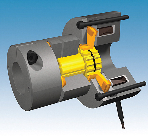
Mayr’s new ROBA-stop®-M fast-switching brake is optimized for extremely short switching times.
The main focus of this application, however, is the extremely quick switching behavior of the brake. On power failure or emergency stop, the fall path of the carriage is an important consideration. The fall path is mainly dependent on the brake switching times and so it’s been optimized especially for short switching times. The fact that the switching time is halved reduces the fall path by 75%. In many cases, this is enough to prevent critical damage to machine components or workpieces after a power failure. Mayr’s ROBA-stop®-M fast-switching brake also increases safety. In contrast to an integrated motor brake, where the braking torque is transferred via a coupling, the fast-switching brake acts directly on the ball screw spindle. This means that the motor can be removed without the loss of braking function.
Mayr
www.mayr.com
::Design World::
Filed Under: Factory automation, Brakes • clutches, INDUSTRIAL SAFETY SYSTEMS, Motion control • motor controls



Tell Us What You Think!