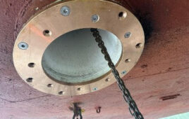
After buzz squeak and rattle testing (BSR) analysis, an OEM discovered failures in its Seating System. The issues included axial play in the seats and noise emanating from the seating system assembly. The OEM vendor reported that the issue was the seat mechanism of its Technymon MR-5 Sliding Bearing.

The solution — introducing an entry radius and deforming the pre flanging area 80° — resolved the issues without impacting the material thickness and hence triggering any incremental material or assembly costs.
The MR-5 Sliding Bearing in question is comprised of a zinc plate, low carbon, steel, and thick PTFE tape. The tape prevents metal-to-metal contact and provides self-lubrication. It is used in seating mechanism pivots including the upper and lower height adjuster pivots, folding pivots, the back-rest angle adjustment, (recliner mechanism) and the headrest. These bearings are designed to accommodate high static load, eliminate noise, and dampen vibration. They enhance the comfort level as well as extend the life span of the system components.
But after opening the seat mechanism for further inspection, the OEM also discovered that the bushing PTFE tape was missing. The absence of PTFE tape contributed to the axial play and direct metal to metal between the shaft and the backing layer of the low carbon steel, causing the noise. That’s when the company chose to incorporate Technymon MR-5 Bushings.
As part of its investigation, the Technymon technical team visited the OEM’s site and collected the MR-5 Sliding Bearings, verifying the PTFE tape adhesion test with steel. The team concluded that the integrity of the samples — its adhesion and dimensions— were acceptable.
Next, the team analyzed the customer’s components, including the shaft (shoulder bolt) and housing (link). After exhaustive testing, the technicians concluded that the shaft (shoulder bolt) was missing its entry radius, which was damaging the PTFE tape during the assembly of the bushing inside the housing (link). To address this performance issue, the team recommended incorporating an entry radius on the shaft.
After this modification was introduced, the technical team revisited the OEM’s site and discovered that during the assembly process, the housing (link) fitment for the pre-flanging operation was faulty. Consequently, during the bolt tightening (shaft) to fix the link with seat mechanism sliding bearing backing layer, which is made up of Low carbon steel, was cracking at the pre-flanged area and damaging the PTFE tape.
To address these issues, the OEM recommended replacing the material with a thicker low carbon steel backing to prevent cracking. Still, the Technymon team advised the client that this would increase the product cost.
Next, the team noticed that the customer was assembling the 90° pre-flange forming in one step and recommended that it be changed to two steps, which would preserve the integrity of the material without compromising the PTFE layer. This solution posed an assembly cost increase.
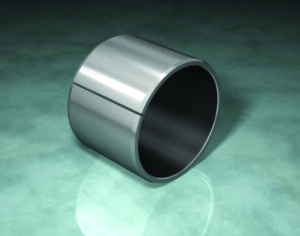
The MR-5 Sliding Bearing in question is comprised of a zinc plate, low carbon, steel, and thick PTFE tape.
Finally, working with the OEM’s technical team, the Technymon technical team arrived at a cost-free solution: Deform the pre-flanging area with a maximum 80° deformation in one step, with the remaining deformation during the bolt tightening to be fixed at 90°.
The problem arose when a heavy load was applied against the link surface on the sliding bearing, which resulted in uneven PTFE deformation. This uneven deformation caused the PTFE to tear, destroying the adhesion of the low carbon steel, and subsequently causing noisy axial play.
The solutions — introducing an entry radius and deforming the pre flanging area 80°— resolved the issues without impacting the material thickness and hence triggering any incremental material or assembly costs.
The OEM produced its seating system with the new solution. Subsequent BSR testing revealed that the changes had proved effective.
Technymon
technymon.com
Filed Under: Bearing Tips