Laser direct structuring (LDS) creates circuit traces on molded thermoplastic components. It is one of the leading technologies for producing cell phone antennas, molded interconnect devices (MIDs), components for medical devices, security shields, automotive sensors, and GPS antennas. LDS can be a lower cost method of manufacture over more traditional methods, with savings coming from reduced assembly times, increased assembly yields, reduction in parts, and reduced time to market. Another savings comes from the reduction of non-recurring engineering costs by designing in the proper tolerances of the structure of lines and spaces from the beginning.

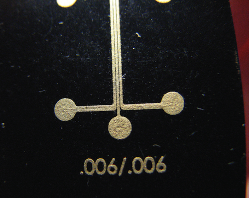
The average width of the plated traces in the PET/PBT sampling was 0.0073-in. (0.1854mm). The average spacing was 0.0048-in. (0.1219mm). The plated traces were over-sized slightly more than expected at 22%.
SelectConnect Technologies used the following techniques for producing LDS MIDs.
Generating CAD files:
Before a pattern can be structured, the artwork must be generated by CAD software. Generally Pro/E or SolidWorks work well because files can be created in STEP or IGES formats. All geometry must be a surface that has a zero height (Z=0-in.). This ensures that the geometry will be processed properly by the laser plotting system software. All modeled surfaces must be continuous. If there are any breaks or discontinuities, these will be reflected in the final structured product.
Overview of the LDS:
Once the laser machine is set up with a program, the pattern is structured onto the plastic part. It is important for the part to be held firmly by a fixture. This allows the laser camera system to identify the fiducials (alignment reference points) speedily. Once the fiducials are found, the laser marks the pattern and a 3D MID is produced.
Plating process:
Take care to ensure LDS components are plated properly. Areas of concern include cleaning solutions, plating bath concentrations, solution temperatures, plating times, and racking. Standard plating thicknesses for MIDs are used for this process.
Measuring equipment:
You should accurately measure the width of the traces and the spacing distances. The goal is to discover how narrow the traces can be at the closest spacing possible without the plating bridging or shorting.
Inspection and measuring can be accomplished using a Scienscope MZ7-PK5-FR-U Dual Arm stand video microscope. It can reliably measure distances in inches through four decimal places. Inspection can be accomplished through an integrated video system. Once an object is in the lens field of view, the image is projected onto a computer monitor. From here, you can measure the distance using the microscope’s software.
Process variables:
There are a variety of materials suitable for the LDS process. The three most common material types are liquid crystal polymer (LCP), polycarbonate/Acrylonitrilebutadiene Syrene (PC/ABS), and polyethylene terphthalate/polybutylene terephthalate (PET/PBT). LCP displays excellent dimensional stability. PC/ABS has good mechanical properties, and PET/PBT has high thermal shape stability.
Laser optimization:
There are three laser setting required for successful laser structuring– watts, kHz, and mm/sec. The settings are unique for each LDS material type.
SelectConnect Technologies
www.selectconnecttech.com
::Design World::
Filed Under: Medical-device manufacture, Lasers, ELECTRONICS • ELECTRICAL


Dynascan is a leading manufacturer and exporter of Video inspection system, video measuring machine. Quality Video inspection system and video measuring machine in chennai and pune.