Computer-controlled fiber aligners help boost throughput in photonics-packaging applications. Before the telecom boom at the end of the millennium, fiber alignment in the manufacture of photonics products was a tedious manual task. Here’s a summary of the first designs to automate the job and what’s possible with today’s technology.

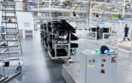
Pre-production bench for silicon photonics chip manufacturing and inspection: The system integrates several hardware components and software for automating assembly and alignment, such as pick-and-place robotics, machine vision or precision positioning devices.
Analog gradient search: The analog-phase demodulation hill-climbing technique worked (and in some cases, still works) for clean, quasi-Gaussian couplings already near optimal alignment. But it locks in on local maxima and flat spots in multimode couplings and imperfect devices with misalignment. Instrumentation based on this principle was popular, though bulky and with too little travel for fully automated fiber alignment.
Digital alignment algorithms: The first digital-gradient search technique in the 1990s aligned fiber-optic devices with motorized linear stages of the day—slow and low-resolution devices with limited synchronization compared to today’s piezoelectric nanopositioners. But these setups were flexible, and their massive motorized positioners worked for the emerging industrial era of photonics.
Note that analog gradient search and digital alignment algorithms didn’t address angular alignment, and new photonic devices made angular alignment a mainstream concern. First, planar waveguides became key to switching and modulating in photonic networks. Second, angular alignment needed automation, as optical switches based on steering of collimated beams necessitated throughput-optimized gimbaling alignment of collimators and other optical elements. Third, confocal optical trains (COTs) in new photonics need relatively precise angular alignment.
These needs, in addition to unabated alignment requirements for high-throughput transverse alignment, drove the introduction of the F-206 hexapod 6-axis fiber alignment system. This instrument combined six actuators with a stictionless kinematic flexure coupling. This component integrated a fast photodetector and a flexible assortment of digital algorithms for autonomous fiber alignment automation in up to six degrees of freedom.

By integrating six degrees of freedom, F-206 facilitates complex alignments like this 10-DOF waveguide MUX/DEMUX packaging.
A key advantage of the hexapod parallel kinematic approach is the ability to cast the rotational pivot point anywhere in space. Conventional stage-stacks are limited to rotating about the fixed mechanical centerpoint of their rotation stages and goniometers. This is defined by their bearings and fixturing structures and cannot readily be moved around. With the hexapod, process engineers gained the capability to place the rotation point about an optical sweet spot with a single software command, a significant advantage for alignment of complex fiber-optic components. Examples include:
- for multichannel waveguide alignments, the rotation can be about the first optical channel
- in collimator-collimator alignments, the rotation can be centered on either collimator’s face
- for COT alignment, the alignment can pivot about its focal point, which might be buried inside a package and only blindly accessible by tweezers.

The F-206 HexAlign hexapod micro-alignment system provides six degrees of freedom of 0.1 m precision motion in a more compact and responsive package.
New hexapod options, new fiber-optic alignment power
Recent advances in hexapod design and controls have now enabled a host of robust, high-load, long-travel hexapods to be deployed for high-throughput industrial alignment applications. Building on previous high stiffness designs and triangulated geometries, these systems offer travel ranges of several centimeters while accommodating loads of many kilograms. These designs are suitable for use in any mounting orientation and offer up to 50% higher acceleration than previously possible. In addition to integrating optical metrology with the hexapods’ six degrees of freedom plus two additional linear or rotary axes of motion, their new controllers integrate data recorders for correlation of optical power with position. 100-x-100-m scans can be achieved in as little as 650 msec with these speedy mechanisms.
Interfacing options have also expanded and improved, with standard TCP/IP and USB ports offering high-speed communications and compatibility with factory automation architectures. New, optional remote-control pad/displays offer hands-off manual operation.
Modular piezofiber alignment engine for transverse alignment and tracking
As the telecom boom crested in the early 2000s, a manufacturer asked the design team at Physik Instrumente to create a cost-effective fiber-alignment platform for coarse-to-fine transverse alignment. The company wanted a simple stack of stages with the NanoCube XYZ nanopositioning stage (for 100 µm of travel in three orthogonal axes with 2-nm resolution).
Three motorized stages would allow many millimeters of coarse positioning to accommodate different devices in the company’s production. The system was software-based (to leverage new fast analog I/O interfaces), modular, open-source and based on LabVIEW. Two main challenges were that the machine had to handle fiber-through-tube designs (which complicate the search for first-light) and irregular coupling cross-sections, which can impede gradient searches. In the end, PI engineers built a machine with a two-step sequence. First, a compact double-spiral scan uses a motorized long-travel stage for first-light capture and rough optimization. Then a fast raster scan (previously impossible without modern piezoelectric positioners and advanced controls), combined with synchronous data acquisition to compile the transverse coupling cross-section and identify the global maximum. This approach would literally align virtually anything in a flash.
The raster-scan approach is insensitive to local maxima. The global maximum can always be observed and selected. This option had been unavailable a decade earlier due to the limitations of the motion devices of that day. Since piezo devices are so fast, why not collect data to localize the global maximum directly rather than inferring the vector to it from the limited data older architectures could provide?
Recently this architecture, called CyberAligner, has enjoyed many advances, including an upgrade to updated versions of LabVIEW and leveraging I/O capabilities provided by today’s multifunction analog/digital hardware.
Physik Instrumente
www.pi-usa.us/products
Filed Under: AUTOMATION, Materials • advanced, MOTION CONTROL


Tell Us What You Think!