Three ranges of voltages are available for cables today. Low-voltage designs—often those used in industrial settings—are rated to 2,000 V or lower. Medium voltage designs range from 2,000 to 35,000 V and high-voltage cables are those rated above 35,000 V.
Medium-voltage cables are commonly used in mobile substation equipment, for distribution of power in industrial settings and in mining to supply power to drills, shovels, haulers, etc., said David Sedivy, Senior Product Manager at TPC Wire & Cable Corp. These cables often come in standard voltages, including 5,000; 8,000; 15,000; 25,000; and 35,000 V.
A common application for medium-voltage cables is in maintenance and repairs, said Sedivy. Utilities personnel use mobile workstations to provide scheduled downtime maintenance for substations or to conduct repairs due to damage caused by a storm, for example.
In addition, industrial facilities might have an in-house team or contractors that install and repair these types of cables for distribution of power, as some facilities have responsibility for some of the power that is coming into them.
Preventing charge accumulations
Perhaps the biggest difference between low- and medium-voltage cables is their construction. Most medium-voltage designs offer extra protection to prevent the build-up of potential charges anywhere along the cable.
A typical, single-conductor, low-voltage design is usually constructed of the following:
• An aluminum or copper conductor,
• Insulation and
• Jacketing
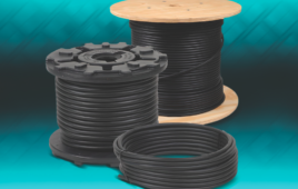
Medium-voltage designs are usually constructed as follows:
• An aluminum or copper conductor,
• A conductor shield—which is usually made of some type of semiconductor material,
• Insulation,
• Insulation shield, which again can be a semiconductor or a metallic braid or tape, and
• Jacketing
The conductor and insulation shields help reduce the effects of imperfections on the cable or the effects of the cable coming in contact with a ground potential, where voltage can accumulate. Electricity will always find the lowest point of resistance, so the semiconductor, copper tape or metal braid is there to spread out the charge more evenly. “No application or cable is perfect so there are going to be points on that cable where there might be a slightly thinner jacket or contact with ground, so you might have a lower point of resistance,” Sedivy said. “That’s where a charge will try to accumulate because it’s trying to find ground potential. And without the conductor shield or the insulation shield, these charges can build up and discharge.”
This safety mechanism prevents possible discharges that can damage the cable, equipment or worse yet, cause injury.
Unshielded designs

A variation of the typical medium-voltage cable is the unshielded jumper design, which features a conductor, a conductor shield, insulation, and jacket. They are usually used inside equipment, where space is at a premium and where they will only be accessed by authorized personnel.
Unshielded jumper cables should only be specified by end-users who fully understand their restrictions and who do not need a shielded design, cautioned Sedivy. “Where I’ve seen them used most is in manufacturers of original equipment that are installing in tight spaces and very compact areas so they need something a little bit easier to work with and they are controlling access to their equipment,” he said. “This is the type of equipment or application where if there’s a problem, you’re going to call a trained technician, not try to fix it yourself.”
For the majority of applications, end users are looking for National Electrical Code (NEC) rated designs. According to the NEC, medium voltage applications must use a type MV cable. The majority of these cables are stiffer because they use coarser stranding and copper tape or braid insulation that can make them difficult to work with as far as flexibility. On the other hand, utilities have their own codes to follow and are not necessarily required to follow the NEC, so they can use Type SH shielded cables.
Materials
Copper and aluminum are the two main conductor materials. Copper is used mostly in medium voltage designs, while the lighter weight aluminum is used more often in high voltage cables.
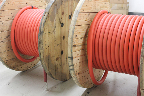
A variety of materials are used in medium voltage jacketing. Cross-linked polyethylene or XLPE is one of the most recommended, but ethylene propylene rubber or EPR, chlorinated polyethylene or CPE, and Neoprenes are also used. The most important factor cable manufactures must consider when selecting a cable and its jacket material is whether the wall thickness is suitable, especially according to UL and CSA standards. The end-user should consider how the jacket will hold up to its environment, such as sunlight, heat, cold, etc.
Finally, different design requirements exist if medium voltage cables are going to be direct buried. For example, if there is a fault the copper tape or copper braid insulation shield must carry a current. As a result, the cable must have a specified area or mass for the shield to be able to carry a fault if something goes wrong.
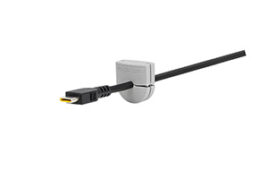
Termination is critical
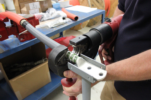
When purchasing medium voltage cable, most companies like TPC will build the complete assembly for the customer and put terminations on one or both ends for them. “Terminating a medium or high voltage cable is not only a process but an art,” Sedivy said. “You can give someone the instructions on how to terminate these cables but that in itself really isn’t enough. They really need to go through training because there are certain techniques that you have to follow and that you have to know.”
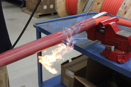
For example, even the smallest imperfection in these cables—a speck of contamination, a nick or a cut strand that is stuck where it doesn’t belong—can lead to a failure of the cable. It can take skilled personnel anywhere from a half-hour to a full hour to terminate an assembly because everything must be as exact and precise as possible. Sedivy said that TPC also puts the cable through a high-pot test, to test the integrity of that termination and ensure that there isn’t a path for electricity to find its way through.
“With medium voltage cables, everything gets amplified so any little problem can become a big problem,” Sedivy concluded. “There is no room for error.”
TPC Wire & Cable Corp.
www.tpcwire.com
The post When to use medium-voltage cables appeared first on Wire and Cable Tips.
Filed Under: Cables + cable management, Wire & Cable Tips