By Dave Bird
Dave Bird is the Business Development Manager for Balluff, Inc.
The strategy of “Error Proofing in manufacturing,” — eliminating as many opportunities for quality problems as possible — can affect us all. In the fall of 2000, I purchased a 2001 minivan that I thought would provide years of trouble-free service. At 48,000 miles the transmission failed, which the manufacturer replaced under warranty. In September 2007, with 103,000 miles on the odometer, the replacement transmission failed in the middle of a dangerous intersection.
Information I gathered afterword hinted that an aimed port designed to deliver transmission fluid lubrication to a gear was misaligned, causing slow death to the transmission. This misalignment made 1.2 million transmissions suspect in two vehicle models built by the same manufacturer in two model years. In September 2002, the manufacturer recalled 24,000.
What does this mean if the gear lubrication example is accurate? It took roughly 5 years for the company to uncover the true root cause of failure, creating lost customer goodwill in the process. Had every component in the transmission gone through 100% inspection during the assembly process, maybe the manufacturer could have prevented such loss.
One way to guarantee 100% inspection in this example would have been through the clever placement of a sensor that would assure that the lubrication port was aimed correctly as part of a basic manufacturing step in the assembly of the transmission.
Sensor-driven error proofing
Total Quality Management, Lean Manufacturing, Error-Proofing, and Poke-Yoke describe various programs for eliminating mistakes from the manufacturing process. Many people are recognizing that the most effective, cost-efficient, error-proofing programs integrate sensors in the manufacturing process to eliminate errors through 100% inspection. Post-production checking stations and human based “eyeball checks” in post production can’t possibly verify that all components going into a product are perfect nor in the right location with proper orientation.
Manufacturing high-quality parts means much more than building a quality product. The right product must be queued in the correct sequence and delivered at the right time—time after time. The role of sensors now not only relates the quality of parts or products being manufactured, but directly to overall system efficiency. This new situation increases the importance of sensors and RFID systems as critical tools that increase the value of a manufacturer to its client.
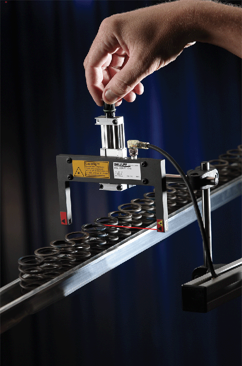
Assemblies that integrate thru-beam, retro-reflective, and diffuse-reflective devices in red, infrared, or laser emission types sense the presence of metallic and non-metallic components. These sensors have greater sensing ranges, and you can place them further away from the detection target.
Today, you can select sensors as your primary choice to increase the quality of the product itself. Leading manufacturers use sensors to locate presence of parts or sub assemblies and to ensure that the part or product is made correctly to customer specifications. Moreover, they can give this information as an integral part of each step in the manufacturing process, not just after assembly as a quality check.
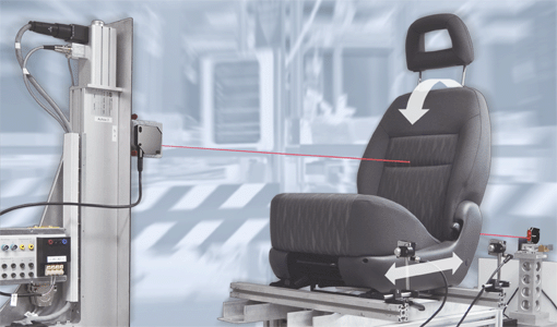
With analog sensors, you can precisely gauge, measure, and position parts and processes. These sensors supply continuous voltage or current output to the control.
Meanwhile RFID tracking within and between islands of automation track what has happened, what has gone right, what has gone wrong, and what needs to be done to correct a glitch in an individual component as well as a process step.
Machine designers need to be aware of this new development in manufacturing. Their designs should incorporate the new role of sensors so that manufacturing machines can easily support error-proofing functions on the line without undue and expensive modifications in supplied production equipment. Here’s a look at what different sensors offer.
Discreet sensors
Discreet “On-Off” inductive proximity sensors are inexpensive, off-the-shelf devices that validate proper metallic parts and the presence and orientation of components during the assembly process. These devices detect metallic tabs, flanges, nuts, the presence or absence of holes, component nesting, pallet transfer, and metal material progression. Tubular sizes from 3 mm in diameter with a short sensing range (0.5 to 1 mm range) to very large sizes with sensing ranges to 120 mm (large metal panel detection) are cost effective components that are simple to integrate into any manufacturing machine or process.
Generally speaking, the smaller the inductive proximity sensor, the smaller the sensing range, but the greater the switching frequency. A small 3 mm diameter tubular inductive type in-flush (shielded) format may only sense a part or a feature 1 mm away, but can switch on and off at 5,000 Hz (5,000 times on and off per second). These features are ideal for gripper, pick-and-place robotic applications for small size and high speed switching.
Analog sensors
Analog sensors supply continuous voltage (0 to 10 V) or current (4 to 20 mA) output to the control. This lets the user precisely gauge, measure, and position parts and processes. Some models have continuous analog feedback as well as three discreet built-in set points that are programmable anywhere in the range capability of the analog sensor (“High-Low”, “Go-No Go” gauge capability) in a self-contained unit.
Photoelectric and analog inductive sensors suit short range analog sensing. For longer-range sensing, long-range analog devices (to 50 mm) or TOF (Time-of-Flight) sensors with up to 6 m of sensing range are suitable.

Misalignment, vibration, and mechanical hits are no longer a concern in some applications that use new “L” and “U” shaped infrared, red emission, and laser,self-contained thru-beam units because these sensors straddle the detection area.
Self-contained thru-beam fiber optics
Thru-beam sensors are dependable, and thru-beam fiber optics (with both plastic and glass bundles) are popular in many manufacturing scenarios. Thru-beam fiber systems, however, can vibrate out of alignment and often become targets for fork trucks, plus they easily incur mechanical damage. You must take bending radii into consideration. They also require a separately mounted amplifier.

Color sensors verify correct installation and match of component color in a variety of applications including this interior automotive trim application.
New “L” and “U” shaped infrared, red emission, and laser, self-contained thru-beam units are conducive to many error-proofing applications such as part presence, height verification, or feeder bowl part flow verification. If the emitter and receiver are built into a rugged metal frame, you can straddle the unit over the detection area without concerns about misalignment, vibration, or mechanical hits.
Color sensors and color matching
Whether it is automotive trim, “O” ring color detection, carpet, or even food applications, color sensors verify that you installed and matched the correct component color during the manufacturing process. High-end color sensors can reach out to 100 mm. They have 15 hexadecimal discreet outputs, but many low cost, effective, off-the-shelf RGB (red, blue, green) devices with super white light emission can detect three colors or shades of color with accuracy in memory.
UV tracing
Luminescence or ultraviolet sensors emit a beam of light in the ultraviolet spectrum. You must add a target material to the part you want to detect and validate, or UV properties must be present naturally in the target material. UV tracer materials are invisible to the human eye, do not interfere with product integrity or aesthetics, and are inert. When you add them to small components prior to assembly, they react to the UV emission of a sensor, confirming presence.
Tamper-proof seals on pharmaceutical bottles contain UV tracer materials that are validated during packaging. Certain 2-liter soda bottles also contain an alignment strip on the ends of the labels for proper application after bottling with liquid.

Luminescence or ultraviolet sensors detect the presence of UV in tracers applied to the target material. If properly applied, UV tracers make dependable targets for the UV sensor. In many applications, UV sensingis just as reliable and much more cost-effective than machine vision.

Manufacturers often use error-proofing sensors to verify and validate build information on RFID tags. RFID systems store and build data on a small data carrier permanently affixed to a pallet to identify different product versions.
Track build information
Flexible manufacturing requires constructing various product variants on the same line. Because different product versions have unique features to error proof, manufacturers must identify the exact version being manufactured. RFID systems that store and build data on a small data carrier, such as a “chip” or “tag” permanently affixed to a pallet suit this purpose well.
Before assembly begins, the tag receives build information that instructs all downstream processes of the exact version being manufactured. Correct assembly is verified and validated by comparing the build information to what the error-proofing sensors detect.
Sensor application specificity and sensor protection
Most often robots, clamps, hydraulics, pneumatics, and machine beds do not cause down time. It is the vulnerable devices like sensors and connectivity systems that fail because they sit on the periphery of equipment in hostile environments with minimal protection.
Sensor manufacturers develop each sensor for a specific customer’s need. It is unwise to expect that a genteel sensor for a pristine clean room assembly operation will perform equally well in a hostile manufacturing environment such as welding. Applications that involve nesting, Poke-Yoke, and clamping sensors in robotic welding, or other harsh environmental applications can experience major systemic sensor failure. Enormous quantity production environments expose fragile plastic brackets of the electronic device to impact, burst weld heat, and weld debris. Cables are often clipped and frayed. It is common to see customers consume between $8K and $70K per month on replacement sensors and connectivity systems in welding cells. Other robust manufacturing scenarios reflect the same type of consumption.
For example, nesting, Poke-Yoke and clamping sensors found in robotic welding are very often found with fragile plastic brackets exposing the electronic device to impact, burst weld heat, and weld debris. Cables are clipped and frayed. It’s common to see customers consume between $8K and $70K per month on replacement sensors and connectivity systems in welding cells. Other robust manufacturing scenarios reflect the same kind of consumption.
To guard your system, take the following steps:
• Install the correct application-specific sensor from the beginning, such as coated sensors, robust sensing faces, high temperature types, and so forth, for clamping, nesting, and Error-Proofing applications.
• Use heavy metal bunkering and protective mounting systems to mount sensors that vaporize or disintegrate in the heaviest of weld environments, such as MIG and TIG processes, instead of inexpensive, lightweight, mounting systems.
• Use cables and connectivity from the beginning, such as TPE types.
• Protective silicone sheathing and wrap can extend cables and connectors harsh manufacturing scenarios, but are almost never is integrated from machine build.
Regardless of the industry in which your machines are designed to function, many off-the-shelf, cost-effective, easy-to-employ sensors can error proof your customer’s process. With these sensors and clever application expertise, you can achieve 100% inspection of components for presence, absence, feature detection, measurement, and tracking with high repeatability and reliability.
Balluff, Inc.
www.balluff.com
: Design World :
Filed Under: SENSORS, TEST & MEASUREMENT

Tell Us What You Think!