In Part 2 of this article, the author will show how Finite Element Analysis (FEA) can be used to perform a more detailed study of how the new wear band will react to the stresses it will be subjected to during installation and operation.
Introduction
Part 1 of this article discussed the function of wear bands in heavy equipment and introduced the steps required to analyze the stresses they would be subjected to. It provided the equations necessary to determine the modes of failure and to calculate an acceptable safety factor for the band. In Part 2 of this article, the author will show how Finite Element Analysis (FEA) can be used to perform a more detailed study of how the new wear band will react to the stresses it will be subjected to during installation and operation.
Additional Modeling Techniques
Step 6 involved additional modeling techniques that were employed in the design analysis of the new wear band. Initially, Finite Element Analysis (FEA) was performed on a symmetrical quarter-sectioned assembly made of 301 full-hard stainless steel. This required setting it up as a custom material and a special contact set for shrink fit. The simulation, which required 45 minutes to run, yielded a maximum stress of just 65 psi.
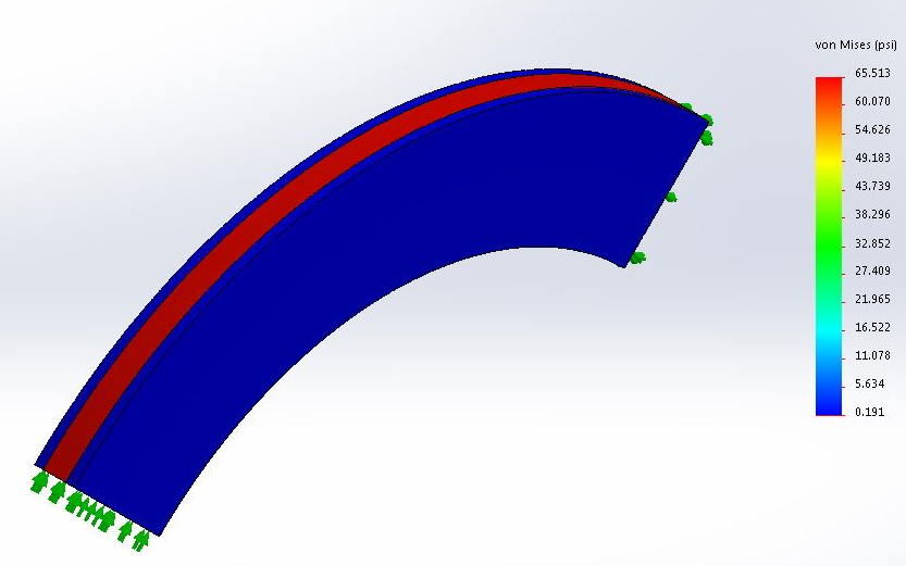
Fig. 4 Initial 3-D FEA results
It should be noted this model reported Von Mises stress, even though direct hoop stress was in the Y-normal direction. FEA showed the difference between the two was negligible.
Due to the time required to run a full 3D model, a 2D FEA model was used, yielding the same results.
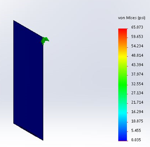
Fig. 5 Initial 2-D FEA results
Given a yield strength of 66,700 psi, a stress of 65 psi gave a factor of safety in excess of 1,000:1. Yet our mathematical model gave us a stress of 28,000 psi. FEA can be relatively easy to execute, but it is also easy to incorporate errors into the study.
The 301 full-hard stainless steel had to be set up as a custom material for the simulation. It was found the modulus of elasticity was improperly set up. Specifications from the supplier reported it at 28 x 103 ksi, but the FEA requires it to be input in psi, or 28 x 106. When the values from the supplier were input directly into the software, an error of a significant order of magnitude was introduced. However, because the mathematical model had been previously run, it provided an indication that the FEA had an error.
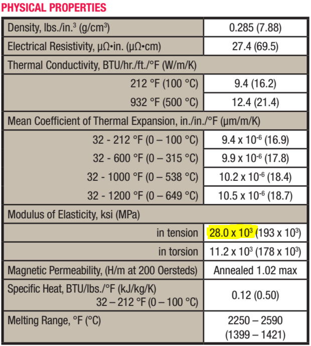
Fig. 6 Physical properties of 301 full-hard stainless steel
Rerunning the simulation with the correct modulus of elasticity yielded a maximum stress of 65,000 psi, 2.3 times higher than the mathematical model and dangerously close to the yield point. Again, there was an inconsistency noted against the mathematical model that had to be resolved.
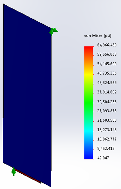
Fig. 7 FEA results with updated modulus of elasticity
The results shown in Figure 7 were based on a shrink fit modeling method within the FEA software. As an alternative, a direct press-fit FEA method was utilized and yielded a maximum stress of 39,000 psi, considerably lower than the shrink fit model and closer to the mathematical model.
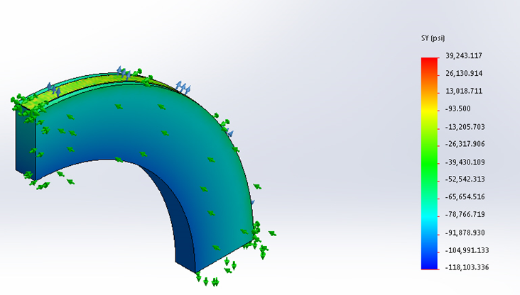
Fig. 8 FEA based on press-fit method
At this point we had three different sets of values for maximum stress and factor of safety:
Mathematical Model Press Fit FEA Shrink Fit FEA
Maximum Stress (σC) 28,500 psi 39,000 psi 65,000 psi
Factor of Safety (FSSUT) 3.1 2.4 1.36
The above results are significantly different, raising the question as to which method provides the correct design data. This leads to the seventh step of the analysis process, physical testing.
Since a 44.875″ shaft was not available for testing, wear bands were analyzed and tested for a 16.00″ shaft. The shrink fit FEA method was suspect, so the inside diameter of the wear ring to be tested was selected to result in failure (safety factor <1) based on the shrink fit FEA method. To help ensure the safety of the technicians, it designed for failure by yielding rather than brittle failure, thus using the yield strength of the material as the threshold of failure. It was determined that an inside diameter of 15.947″ would yield the following results:
Mathematical Model Press Fit FEA Shrink Fit FEA
Maximum Stress (σC) 4,000 psi 6,500 psi 77,000 psi
Factor of Safety (FSSUT) 22.1 13.6 1.147
Factor of Safety (FSSY) 16.7 10.3 0.90
A wear band with a 15.947″ I.D. was produced and installed on the shaft and observed over a period of 48 hours. There was no failure or visible necking down of the material. This indicated that the shrink fit FEA method did not produce accurate, reliable results.
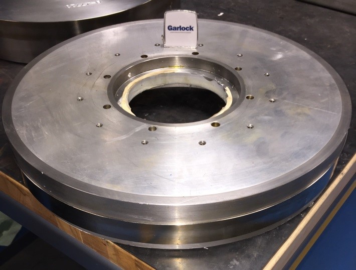
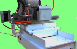
Fig. 9 Wear band installation test
With the shrink fit FEA method ruled out, we were left with the mathematical model and the press fit FEA method to consider. These two methods were close enough that one could not be easily ruled out through testing. With the mathematical method showing a factor of safety against total failure of 3.1 and the press fit FEA method 2.4, design decisions were made to improve the level of confidence against this form of failure.
The amount of interference between the wear band and the shaft has a direct relationship to the factor of safety against slippage and an inverse relationship to the factor of safety against total & yield failures. Since the factor of safety against slippage was higher than needed, it was determined that the amount of design interference could be reduced, in order to provide a higher level of confidence against the other forms of failure.
Additional tests were conducted to determine the tensile strength of the welded area and the quality of the welds. Tensile tests were conducted on both the base material and welded sample at various stages of the process. Microstructural analysis to gauge weld quality revealed good penetration and minimal porosity. This involved sectioning a welded sample transversely and polishing it for visual inspection under high magnification.
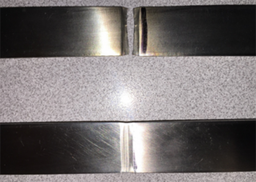
Fig. 10 Pull test samples
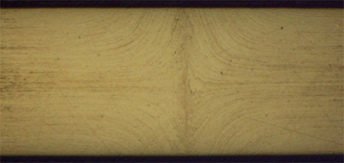
Fig. 11 Microstructural analysis
The induction heating process for shrink fitting the wear bands required special equipment. For our tests, we used an Ambrell EASYHEAT 8310LI solid-state induction power supply. See video on temperature increase and shaft installation at Video Link 2.
Conclusion
In summary, wear bands provide an appropriate sealing surface for shafts that do not or no longer meet the requirements of the application. Our analysis method assured their performance, both from an operational and safety perspective. It is important to note that FEA was just one component in this analysis, which involved a 7-step process to define stresses, determine failure modes and factors of safety, research and apply different methods and models, utilize additional modeling techniques, and conduct functional or physical testing.
References
1 Thick-Walled Cylinders and Press Fits, W.H. Dornfeld, 2004.
Filed Under: Rapid prototyping