Viscoelasticity, or the inherent ability of plastic and elastomer materials to move with load and deformation, is rate-dependent behavior and is most commonly known as creep and stress relaxation. Stress relaxation is the decay of stress over time when placed under a constant strain. Creep is the increase in deformation or strain under a constant load and stress. Stress relaxation and creep can affect sealing capability as well as seal shape.
Stress relaxation reduces the force exerted by the seal to the sealing surfaces. Common terminology for this effect includes compressive stress relaxation (CSR) and aging. CSR is typically a material’s performance tested at time and temperature to measure the stress relaxation in compression. Aging is a general term used to describe a change in sealing stress or force, of which stress relaxation is one of the factors causing this behavior.
Creep significantly affects sealing by changing the shape (deformation) of the seals, which changes sealing stress distribution. Terms like extrusion, cold flow and set often describe these shape changes related to creep. Extrusion is typically movement of seal material into the small clearances of a rod housing or piston. Cold flow is another term for creep that defines shape change of the seal over time. Set is deformation under stress or load, part of which is due to creep.
We focused on measuring linear viscoelasticity for the FEA analysis. Linear viscoelasticity follows a principle of superposition where the relaxation (or creep) rate is proportional to the instantaneous stress (or strain). In this case, stress (or strain), when normalized by the instantaneous value, will follow the same variation with time, showing independence to their instantaneous values.
Material models in FEA
The elastomeric materials were modeled in two steps using hyperelastic material models for instantaneous state of stress and using time dependent function, R (t) = [1- ? {ai (1 – e-t / ti)}] as described in the Appendix.
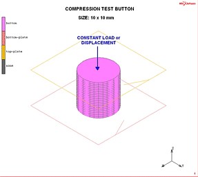
To test whether FEA analysis is an accurate predictor of seal material behavior, Trelleborg engineers tested various materials shaped as buttons and rings. They used an Instron testing machine to test buttons made of Turel® BAE at 12.7 mm/min and the Turcon® T46 buttons at 1.27 mm/min.
Modeling was done using uniaxial stress/strain and stress (or strain)/time test data. The elastic-plastic materials were modeled in the same way, except their instantaneous state of stress was modeled using uniaxial elastic constants and stress/strain.
Eight materials (Turcon, Zurcon, Turel among them) in the shapes of buttons and rings were tested under compression creep and relaxation and then underwent finite element analyses. We found that the FEA results compared with the test results.
An Instron testing machine was used to test the elastomer buttons at 12.7 mm/min and the plastic buttons at 1.27 mm/min. It also tested the elastomer O-Rings at 12.7 mm/min, and the plastic rectangular rings at 1.27 mm/min.
FEA analyses of test buttons and rectangular O-Rings were performed using the material test data of the buttons, and the results were compared with their test results. FEA codes 3, 4 MARC® and ABAQUS were used in the analyses. A good correlation was found indicating the validity of the FEA processes.
Validating the FEA procedures
To validate the FEA procedure, we first compared the FEA results of the button sample with the button test data and then compared the FEA results of a ring, using the material test data, with the ring test results. (The authors tested all eight materials, but this article will focus on the plastic Turcon® T46 and the elastomer Turel® BAE.)
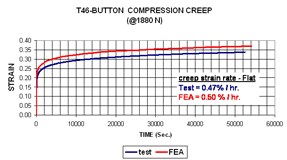
The results of the FEA analysis and those of the physical test for creep and strain of the Turcon® T46 button were almost identical, as shown in the graph. The slope, or rate of change of strain, after the initial or instantaneous strains, is almost equal. From these data, the engineers concluded that the FEA process appropriately modeled the creep behavior.
For Turcon® T46 — the button was tested under a compressive load of 1880 N held constant for about 15 hours. The instantaneous stress-strain data and the creep strain data were used in the FEA.
The FEA and the test results were almost identical. The slope, or rate of change of strain, after the initial or instantaneous strains, is almost equal. Therefore, we concluded that the FEA process used appropriately modeled the creep behavior.
The button was tested under compression strain of 15%, held constant for about 10 hours. The instantaneous stress-strain data and the shear modulus relaxation data converted from the
uniaxial stress-time test data were used in the FEA.
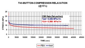
This graph compares the results of the FEA analysis with test results for the Turcon® T46 Button for instantaneous stress-strain data and shear modulus relaxation data.
The ring was tested under compressive load of 6000 N held constant for about 14 hours. The FEA creep strain rate of the ring matches closely with the test value, signifying that the FEA process could be used to predict the viscoelastic behavior of the seals with confidence.
The ring was tested under compression strain of 15% held constant for about 15 hours. The instantaneous stress-strain data and the shear modulus relaxation data converted from the uniaxial stress-time test data of the Turcon® T46 button were used in the FEA.
A closer look at a part
We then examined viscoelastic effects through FEA analysis on the Trelleborg HP-20 seal. HP20 is an elastomer and metal rotary shaft seal used in high-pressure hydraulic motors. Its material is affected by viscoelastic behavior.
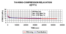
The graph shows the comparison of instantaneous stress-strain and the creep strain test data of the Turcon® T46 ring.
The seal was analyzed at temperatures 23° C and 205° C by ABAQUS using the axi-symmetric model. The elastomer used was Trelleborg material DE15F2684, an HNBR with 90 durometer value. The stress-strain data at two temperatures was used to model the hyperelastic material by Ogden method, and the relaxation data was used to model the material for Prony constants. After assembly a pressure of 5000 psi was applied on the top surface of the seal. Two analyses were carried out at these two temperatures.
Maximum sealing stress at assembly is at the corner node 24 of the seal and is equal to 2284 psi. At the node 110 this stress is equal to 650 psi.
Maximum sealing stress at assembly after relaxation at 1000 minutes is at the corner node 24 of the seal and is equal to 1354 psi, giving a decay of 40%. At the node 110 this stress is equal to 373 psi, showing a decay of 43%.
Maximum sealing stress at assembly after relaxation at 1000 minutes is at the corner node 24 of the seal and is equal to 670 psi, giving a decay of 48%. At the node 110 this stress is equal to 102 psi, showing a decay of 50%.
Conclusions
Based on finite element analyses of various materials of buttons, we found that the creep and relaxation results were verified with the test data, validating the FEA procedure. O-Rings made of these materials were analyzed and tested, and the methods were validated by verifying the viscoelastic FEA results with the test results.
The following graphs shows various stresses of an HP-20 seal. Maximum sealing stress, for example, can be found at assembly at the corner node 24 of the seal.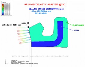
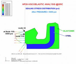
We modeled and validated the effects of creep for a range of materials with an acceptable level of accuracy. We conclude that we now have a robust tool that lets us better understand creep and its effects. In applications where extrusion, set, or cold-flow are the primary areas of concern regarding the performance of the seals, we demonstrated the value of this technique to predict the creep-related behavior.
Trelleborg Sealing
Solutions, N.A.
www.trelleborg.com
This material is excerpted from a white paper, Viscoelastic Effect on the Performance of Elastomeric and Plastic Seals by Finite Element Analysis (FEA) Method, and discusses the results of testing on one plastic and one elastomer material. To read the results of the other materials please read the full paper at: http://resources.designworldonline.com/FEA
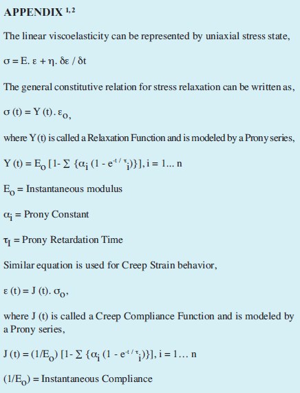
Definitions
Percentage change in total strain is defined as the increase in total strain at any time from the instantaneous strain, divided by the instantaneous strain and multiplied by 100. Creep strain at any time is defined as the change in the total strain at that time from the instantaneous value. Creep Strain Rate (on the curves) is defined as the difference in percentage strain between time t2 and time t1 divided by (t2-t1).Percentage change in stress (relaxation) is defined as the decay in stress at any time from the instantaneous stress, divided by the instantaneous stress and multiplied by 100. CSR rate (on the curves) is defined as stress relaxation between time t2 and time t1 divided by (t2-t1).
::Design World::
Filed Under: Software • FEA, Materials • advanced


Tell Us What You Think!