In Part One of this article, we introduced the basic concepts of flexible heaters and the finite element analysis techniques that can be used to determine the size of a heater needed for a particular application. Here, in Part Two, we will discuss material selection and techniques for testing and verifying the design.
Modeling/Material Selection
The groundwork of any FEA simulation requires modeling of the component or assembly in question. In a flexible heater application, this would most commonly include modeling of the heater and any other components that directly interface with the heater (heatsinks for instance). For the specific example of this analysis, a simulation was completed for the same profiled and uniform flexible heaters from figure 1 from Part 1 with both mounted on identical 6” diameter and 0.5” thick borosilicate glass discs. In addition to modeling the components in question, it is necessary to provide the FEA simulation software with material characteristics for all components being simulated. For heat transfer simulations, it is critical that the software is using the correct density and thermal conductivity value for each material.
Testing Parameters
In an effort to effectively compare the FEA simulation to real-world values, the following testing parameters were utilized in both the real-world experiment as well as the FEA simulation.

Table 1: Testing Parameters
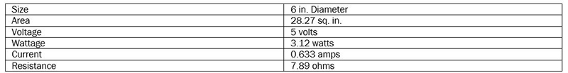
Table 2: Uniform Heater Specifications
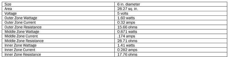
Table 3: Profiled Heater Specifications
Test Setup
Both the uniform flexible heater and the profiled flexible heater were mounted to the backside of each 6” borosilicate glass disc. The glass discs were mounted to four ceramic stands with minimal contact to mitigate heat transfer from the glass discs to the stands holding the disc. The front face of the glass discs were coated with a matte black paint to ensure a clear image with the thermal imaging camera. The heaters were simultaneously supplied with 5 volts and warmed-up for a total time of ten minutes (600 seconds). At ten minutes, thermal images of the front face were taken of both the uniform and profile heater – the thermal images are a representation of the heat transferred through the glass disc from the heater to the front face of the glass disc.

Left Figure 3: Heater mounted with standoffs to back face of disc; Right Figure 4: Front face of disc coated with matte black
Forward Looking InfraRED (FLIR) Thermal Imaging/Emissivity
FLIR thermal imaging devices convert infrared wavelength energy into a visual display that operates in the visual light spectrum. Infrared wavelength energy is typically radiated infrared energy emitted by a heat source. Emissivity is one of the leading causes of confusion when using any FLIR thermal imaging camera or software. Emissivity represents the efficiency that a specific material has at radiating thermal energy. Emissivity values on thermal imaging devices can be tweaked to better match the reflective characteristics of the material – for shiny or low-emissivity materials; it is common practice to cover the surface with electrical tape or coat the surface with a matte black paint. Electrical tape and matte black paint raise the emissivity correction to 0.94. For reference, human skin has an emissivity value of 0.98 while clean aluminum has a value of 0.10. For this analysis, the glass was coated with a matte black paint; the uncoated glass that the heaters mounted to was not a high-emissivity target for the thermal imaging camera.
Results: FEA vs. Thermal Imaging
An FEA simulation was conducted for both the uniform flexible heater as well as the profiled flexible heater. The results of the simulations are documented below in Figures 5 and 7. Similarly, the thermal imaging camera was used to capture a thermal image of the profiled flexible heater mounted to the borosilicate glass disc. For a relevant comparison, the thermal image was captured after a 10 min warm-up period to match the 10 min timed simulation.
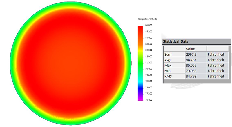
Figure 5: Profiled heater simulation results after 10 minutes and 5 volts input voltage
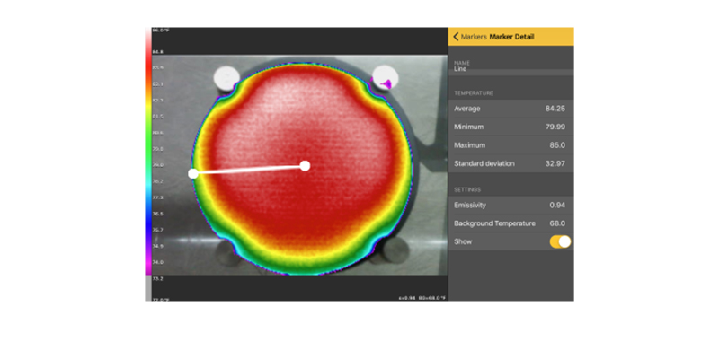
Figure 6: Thermal image of profiled heater after 10 minutes and 5 volts input voltage. Photo Credit: All Flex Heaters
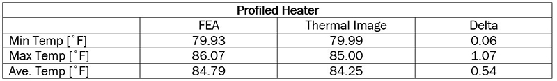
Table 4: Profiled Heater Results: FEA vs. Thermal Image
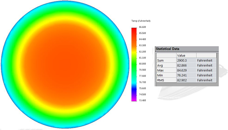
Figure 7: Uniform heater Simulation results after 10 minutes and 5 volts input voltage
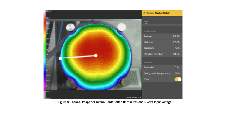
Figure 8: Thermal image of uniform heater after 10 minutes and 5 volts input voltage. Photo Credit: All Flex Heaters
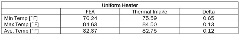
Table 5: Uniform Heater Results: FEA vs. Thermal Image
Conclusion
The demonstrated comparison of FEA heater simulations to real-world heaters shown above provides valuable evidence in the argument to implement FEA simulations into the heater design process for flexible heaters. Assuming the FEA simulation is provided with the proper input variables to mimic the real-world application, there appears to be no obvious reason that the FEA simulation can’t accurately hypothesize the thermal uniformity and power requirements with an uncertainty of less than 5%. Utilizing FEA simulations throughout the design process of a flexible heater can greatly decrease the number of prototyping cycles required to build a heater that meets the needs of a specific application while mitigating developmental costs and manufacturing time.
Filed Under: Infrastructure