By Dr. Boaz Eidelberg, Parker Daedal, Engineered Positioning Solutions
Engineers use 3D to analyze vibration dynamics within a laser scribe machine. The 3D dynamic analysis tool used for this examination may help you select parameters you can use to improve machine operation.
Vibration isolation is commonly used to reduce the shock and vibration transmitted to precision machines from the factory floor. Floor vibrations, on the order of 1 to 100 µm in amplitude and 1 to 100 Hz typically arise from nearby operating machines, moving vehicles and trains, or seismic activity. As floors vibrate they transmit their vibration to the machinery mounted on them. The transmitted vibrations are amplified at the resonant frequencies of the machine and then attenuated at a rate of 40 db/decade. Two methods help attenuate the transmitted disturbances; special floor foundations and vibration isolation devices.

Fig. 1: For tools such as inkjet printers or gen 8 laser scribers, it is not uncommon to have a 10 ton machine mounted on 4 isolation mounts and subjected to inertial forces of 1000 kg moving mass at 2 m/sec and 2 g acceleration in a travel of over 3 m long. These inertial forces, on the order of thousands of Newton, act directly on the machine and excite its motion, which the vibration isolators react to.
The choice of vibration isolation method (active dampers, air mounts and passive elastomer isolators) is based on the level of allowable vibrations at the machine’s point of interest. Active isolators result in natural frequency on the order of 1 Hz, air isolators about 3 Hz, and passive isolators on the order of 10 Hz.
When the machine is mounted on isolators it is subjected not only to the small external vibrations on the order of tens of microns, which are being transmitted from the floor, it may also be subjected to much larger internal disturbances of forces and moments from the accelerating moving masses of its positioning stages.
For high-performance machine tools and process tools, such as inkjet printers or gen 8 laser scribers, it is not uncommon to have a 10 ton machine mounted on 4 isolation mounts and subjected to inertial forces of 1000 kg moving mass at 2 m/sec and 2 g acceleration in a travel of more than 3 m. These inertial forces, on the order of thousands of Newton, act directly on the machine and excite its motion, which the vibration isolators react to.
As the inertial forces and moment act on the machine, which is freely supported by the isolation mounts, the main machine frame oscillates in 6 degrees of freedom, including X, Y, and Z translation and angular rotations of pitch, yaw, and roll. The three-dimensional motion of the machine carries with it the positioning stages and introduces secondary inertial forces and moments on the stages. These secondary forces and moment interact with the moving structural elements of the stages and may cause deflections that interfere with a process, which requires 3D accuracy on the order of microns.
Model formulation: In formulating the model, we define in general two coordinate systems, one fixed to the ground the other fixed to the machine. We then calculate the dynamic response of the machine mounted on isolation mounts, to inertial forces, which originate from accelerating stages. We define the coordinate systems as follows:
X, Y, Z (inertial reference frame) – Right hand, Cartesian coordinate system fixed to the floor with origin at some reference location on the machine base. Y is pointing in the longitudinal direction of the machine, X is in the lateral direction and Z is parallel to gravity. This coordinate system is used to define coordinates of the moving masses and the isolators.
X’, Y’, and Z’ (body fixed reference frame) – A moving Cartesian coordinate system with axes parallel to X, Y, Z and origin at the center of gravity (c.g.) of the machine (not including the moving weights of the stages). This coordinate system is used to write the equations of motion about the machine c.g.
We further define system parameters as follows: (vectors are denoted in bold)
Rcg (m) = Vector representing location of machine c.g. in XYZ coordinate
Rm (m) = Vector representing location of a stage moving mass c.g. in XYZ coordinate
Rm’(m) = Vector representing location of a stage moving mass c.g. in X’Y’Z coordinate
Rf’(m) = Vector representing location of an isolator point of action in X’Y’Z’ coordinate
S (m) = Vector representing travel of a stage moving mass within X’Y’Z’
W (rad/s) = Vector representing angular velocity of the machine in X’Y’Z’ coordinate
F( N) = Vector representing an isolator force on the machine in X’Y’Z’ coordinate
M (kg) – machine mass
I (kg* mˆ2) – Inertia matrix of machine about X, Y, Z coordinate system
m (kg) – moving mass of stage
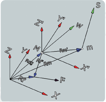
Fig. 2: Coordinate system definition. Color notation:
Red arrows represent coordinate system; blue represents
position vectors; green represents motion vectors; brown
represents force vector.
The coordinate transformation between XYZ and X’Y’Z’ is pure translation and can be written as follows:
Rm’ (m) = Rm- Rcg
Rf’ (m) = Rf -Rcg
Motion profile of positioning stage: We assume that the motion profile of m within the machine is a known function of time as follows:
S” (m/sˆ2) = linear acceleration of m along unit vector s
S’ (m/s) = linear velocity of m along unit vector s
S (m) = Linear displacement of m along unit vector s
Analysis Tool Coordinate System
As shown, XYZ is the inertial frame with origin at the left bottom corner of the granite base. Similarly Xc, Yc, and Zc is the body fixed coordinate fixed to the machine c.g. The angular velocity of the granite is designated by W, and the angular rotations of the machine are designated as P (pitch), R (roll) and U (yaw). Two additional coordinates x1, y1, and z1 and x2, y2, and z2, are parallel to Xc, Yc, and Zc with origins at the home position of Y stage and X stage respectively.

Fig. 3: This illustration of the coordinate system
used in the analysis tool shows a model machine
similar to the machine shown in Fig. 1, including its
notations.
Machine equations of motion
The machine equations of motion in six degrees of freedom are given as follows:
M * d2Rcg/dt2 = Σ Fj – Σ mi* d2Rmi/dt2 (N)
I * dW/dt = Σ Fj x Rf’j – Σ mi* d2Rmi/dt2 x R’mi (N/m)
Where,
M (kg) — machine mass
d2Rcg/dt2 (m/sˆ2) — Absolute linear acceleration vector of machine mass M
Σ Fj (N) — Summation of isolator force vectors
j= 1..4 — Number of isolators
Σ mi* d2Rmi/dt2 (N) — Summation of inertial force vectors of the positioning stages
i = 1.. 2 — Number of stages
I (Kg*mˆ2) — Inertia tensor of the machine
dW/dt (rad/secˆ2) — Absolute angular acceleration vector of mass M
Σ Fj x Rf’j (N*m) — Summation of moments of isolator force vectors about M c.g.
Σ mi* d2Rmi/dt2 x R’mi (N*m) — Summation of inertial force vectors of positioning stages about M c.g.
x — Cross product of two vectors
The absolute acceleration of a moving mass (in our case, it is the moving mass of a positioning stage) with respect to a rotating body (in our case, it is the machine that pitches, yaws and rolls on the isolators) can be shown to be equal to the following expression:
d2R’mi/dt2 = S”+ W x W x R’mi + 2W x R’mi + dW/dt x R’mi – G
Where,
S”= linear acceleration in moving coordinate system
W xW x R’mi = centrifugal acceleration vector
2W x R’mi = Corriolis acceleration vector
dW/dt x R’mi = tangential acceleration vector
G = acceleration of gravity vector (9.8 m/sˆ2 in negative Z direction)
(note that the negative sign is used for G to be applied in the inertial torque equation as shown above in the proper direction)
x = Cross product of two vectors
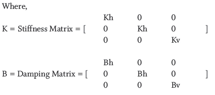
For vibration isolator forces, we assume that each isolator has four parameters as follows:
Kh (N/m) — stiffness in the horizontal direction (X and Y directions)
Kv (N/m) — stiffness in the vertical direction (Z direction)
Bh (N/m/s) — damping in the horizontal direction (X and Y directions)
Bv (N/m/s) — damping in the vertical direction (Z direction)
The isolator forces on the machine frame can then be defined as follows:
Fj = – K * DRfj – B * D dRfj/ dt
DRfj = Displacement vector of isolator j
D dRfj/dt = Velocity vector of Isolator j
The displacement and velocity vectors of an isolator j are given as follows:
DRfj = Rcg + A x Rfj
D dRfj/ dt = dRcg/dt + W x Rfj
Where,
A – angular position vector = < P, R, U > T (T designates Transposed Vector)
P (rad) pitch – angular rotation about X axis
R (rad) roll – angular rotation about Y axis
U (rad) yaw – angular rotation about Z axis
To solve the 3D dynamic equations of the machine, we used a simplified Euler numerical integration with small enough time intervals dT (such as 1 msec) to avoid numerical instability.
To run the following dynamic simulation, we set initial conditions of all state variables at time = 0 and run k= 1.. N iterations, large enough to cover a few low frequency cycles.
Where the numerical linear and angular accelerations at any time T = k * dT are determined from the original equations of motion as follows,
d2Rcg/dt2 (k) = (Σ Fj (k -1) – Σ mi* d2Rmi/dt2 (k -1))/ M
dW/dt(k) = I-1 * (Σ Fj x Rf’j (k -1) – Σ mi* d2Rmi/dt2 (k -1) x R’mi)
The numerical values of the state variables (including velocity and position) are determined by the Euler integration routine. The routine makes successive additions of a previous state variable value to the derivative of the variable multiplied by the small time increment dT as follows:
dRcg/dt (k) = dRcg/dt (k-1) + d2Rcg/dt2 (k) * dT
W (k) = W (k -1) + dW/dt (k) * dT
Rcg (k) = Rcg (k -1) + dRcg/dt (k) * dT
A (k) = A (k-1) + W(k) * dT
Example Problem Using the Tool
Step 1 – Input Mass and Inertia
The first step of the analysis is to enter geometry parameters of the machine base and automatically calculate machine mass and inertia as shown in Fig. 4. Alternatively, mass and inertia may be entered directly.

Fig. 4: The first step of the analysis is to enter geometry parameters of the
machine base and automatically calculate machine mass and inertia. Alternatively,
mass and inertia may be entered directly.
The second step is to enter isolator and stage locations as well as isolator parameters.
The third step is to enter moving mass and motion profile parameters of the positioning stages as shown in Fig. 5.
Once all input parameters have entered the tool, we can run the simulation and observe the state variables and isolator forces as a function of time. We can then study the sensitivity of certain dynamic characteristics to changes in design variable and change the design parameters to yield optimal performance.
Simulation Samples of Machine Dynamics
As shown in Fig 6a, the motion of the machine c.g. in the Y direction is dominant at a level of +/- 6 mm. After 1.2 sec, as the Y decelerates, the machine c.g. reacts by moving forward in the positive Y direction. Then, during a short dwell, the machine c.g. starts returning backward by the isolator spring force in the negative Y direction. After 1.8 sec, when the Y stage starts accelerating backward in the negative Y direction, the machine c.g. once again is reacting in the positive Y direction. Finally, during constant velocity the spring force pushes back the stage to its neutral position with a damping effect of the isolators. The position of the machine c.g. in the Z direction is changing as the moving mass of the Y stage changes its location and causes the machine to pitch.
Fig. 6a shows simulated results of machine c.g. linear motion. The results indicate max displacement of 6 mm in the Y direction, 2 mm in the Z direction and negligible movement in the X direction. The results also indicate a characteristic M shaped profile at end of Y travel. This profile is the result of inertial forces during deceleration followed by a short dwell and acceleration in the opposite direction.
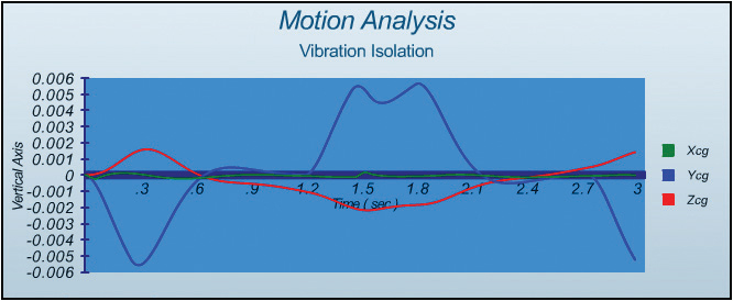
Fig. 6b shows actual test results of Y c.g. motion of a similar size machine running under similar acceleration and velocity. As shown, the motion profile and the amplitude resemble the simulated results.

Fig. 7 shows that the forces of all isolators in the Y direction are virtually identical to each other as they are acting in the same direction to oppose inertial force of moving mass in Y direction with minimal effect due to the short motion of the X stage.

Finally, Fig. 8 shows the dynamic profile of the isolator’s forces in the Z direction. It is interesting to note that isolator 1 and 3, as well as 2 and 4 (not shown), which are on the diagonal from each other, are approximately equal and opposite in reaction to the combined pitch and roll of the machine. The natural frequency in Z motion is estimated at 3.5 Hz.

The objective of the 3D simulation tool is to provide quick estimates to the dynamics of precision machines, supported by vibration isolation mounts while reacting to the high acceleration of their positioning stages. The tool can be used to build a better understanding of the machine behavior, optimize machine design parameters for best dynamic performance, size isolator components, evaluate the effect of stage motion profiles and possibly troubleshoot performance problems.
Discuss this on the Engineering Exchange:
Parker Daedal
www.parkermotion.com
::Design World::
Filed Under: Motion control • motor controls, Mechatronics, Shocks + vibration control • gas springs


Tell Us What You Think!