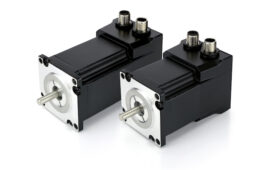
Power-off brakes are commonly used in motion control applications for stopping or holding a load (or both), especially on vertical axes or for emergency stop functionality in servo applications. Power-off brakes are so named because the brake is engaged when power is removed from the system — either intentionally or accidentally. (Power-off brakes are also sometimes referred to as fail-safe brakes.)
While there are many types of power-off brakes, electromagnetic versions are typically used in servo applications. Two designs of electromagnetic power-off brakes — spring-engaged and permanent magnet — are preferred for applications that require high torque, low backlash, and the ability to be customized to the application.
Spring-engaged power-off brakes
Spring-engaged (also referred to as spring-applied) brakes are disengaged electrically via electromagnetic force when power is applied and engaged mechanically via spring force when power is removed. Their construction is relatively simple, with a coil, an armature plate, a friction disc, a pressure plate, springs, and a hub. The hub is connected to the shaft of the motor or component to be braked.

Image credit: Ogura Industrial
To disengage the brake, for normal operation, voltage is applied to the coil. The coil creates an electromagnetic field, and the magnetic flux from this field attracts the armature plate to the coil, which compresses the springs. This releases the friction disc and allows it to rotate, along with the hub and the connected load.

To engage the brake, for stopping or holding, power is removed from the coil. The electromagnetic (attractive) force dissipates and the armature plate moves away from the coil. This decompresses the springs, so they push the armature plate against the friction disc, trapping the friction disc between the armature plate and the pressure plate. This stops (or holds stationary) the friction disc, hub, and load.
Spring-engaged electromagnetic power-off brakes are highly customizable, with the ability to use different spring forces, friction materials, and operating voltages. Some manufacturers of spring-engaged electromagnetic brakes tout their high efficiency, since the amount of power supplied to the brake can be reduced once the armature plate is engaged. (It takes much less power to hold the armature plate in place once it has been attracted to the coil and the springs have been compressed.) It’s also possible, for brakes that have been appropriately sized, to use over-excitation — the momentary application of voltage higher than rated voltage — to reduce the brake’s response time. However, spring-engaged designs typically exhibit some backlash, so may not be suitable in applications where precise stopping or holding is critical.
Permanent magnet power-off brakes
Permanent magnet power-off brakes are disengaged electrically with the application of power and engaged magnetically when power is removed. These designs incorporate both an electromagnetic coil and permanent magnets, as well as an armature plate and a hub.

Image credit: Ogura Industrial
The key to permanent magnet brake operation is the use of magnetic forces from both the coil and the permanent magnets. When voltage is applied to the coil — to disengage the brake for normal operation — an electromagnetic field is created. This field opposes and negates the field of the permanent magnets. Since there is no magnetic field to attract the armature to the coil, an air gap is created between them. And with no contact (and, therefore, no friction) between the armature and the coil, the armature, hub, and connected load are free to rotate.

To engage the brake — for stopping or holding a load — power is removed. With no power to create an electromagnetic field to counteract that of the permanent magnets, the field produced by the permanent magnets acts on and attracts the armature to the coil, and this metal-on-metal contact creates the braking force.
Permanent magnet electromagnetic power-off brakes have a very good torque-to-size ratio and can operate at the high speeds servo motors often require, since there are no moving parts. Permanent magnet versions also don’t exhibit backlash and are typically preferred in high-precision positioning applications. However, these brakes require a consistent, narrow range of current (and, therefore, voltage) to counteract the force of the permanent magnets and release the brake. Conditions that could cause fluctuations in current, such as temperature changes or extreme temperatures* aren’t suitable for permanent magnet power-off brakes.
*The resistance of a metal conductor is affected by temperature (higher temperature equals higher resistance, and vice-versa), and since current is inversely proportional to resistance (I = V/R), a change in temperature will affect the amount of current that is produced.
Filed Under: Motion Control Tips


