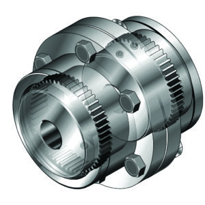
 Gear couplings are designed to transmit torque between two shafts that are not collinear. They typically consist of two flexible joints—one fixed to each shaft—which are connected by a spindle, or third shaft. The gear coupling connects the drive motor to the gearbox in hoist mechanisms, but it can also connect the gearbox directly to smaller wire rope drums using a flanged half.
In terms of their design, gear couplings transmit torque via hubs with crowned gear teeth that are in permanent mesh with the straight gear teeth of the sleeves—a design that provides the highest torque transmission for the smallest size. They also run at high speeds, conform to the AGMA bolting pattern and compensate for angular, radial and axial shaft misalignment.
Ringfeder
www.ringfeder.com
Filed Under: Coupling Tips, Gears • gearheads • speed reducers


Gear couplings not in perfect alignment are subject to wear as the teeth slide on each other. This leads to increased backlash prior to failure, but in a hoisting operation the loading is usually in a single direction so that the backlash is not noticed. Lubrication tends to reduce the wear and extend coupling life, but mostly gear couplings are lubricated once, at installation. The only simple way to monitor gear coupling wear is to start with witness marks aligned on both halves and periodicly check to see how far out of alignment they become. Simpler than checking for backlash and just as reliable.