When we think about actuators, we typically think about linear actuators — devices that move loads in a straight line, driven by a screw, belt, or other mechanical power transmission device. But there also exists a class of actuators that provide rotary motion for positioning a load radially around a fixed axis. While these rotary actuators can be driven by pneumatic, hydraulic, or electromechanical power, we’ll focus here on electromechanical versions.
Electromechanical rotary actuators are designed to move loads in angular increments with very high positioning accuracy and repeatability. Although all rotary actuators can provide up to 360 degrees of rotation, many designs can provide continuous rotation through multiples of 360 degrees.
There are two main design principles for rotary actuators: those that incorporate a mechanical drivetrain — such as a belt or gear — to transfer motion from the motor output to a rotating table, and those in which the motor is directly coupled to the rotating table. In either case, an absolute or incremental rotary encoder is often integrated into the actuator assembly, and brakes are typically offered as standard options. To support the rotating load, most designs use either a rotary ball bearing or a radial (ring-style) crossed-roller bearing.
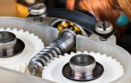
The first type — those that use a mechanical drivetrain — most often use a belt, worm gear, or pinion gear coupled to a servo or stepper motor. In the case of belt-driven versions, gearing (torque multiplication and speed reduction) can be achieved through additional gear components or by using different diameters for the motor and table pulleys.
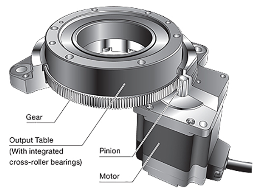
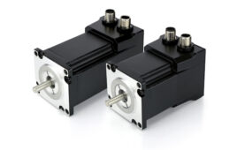
Image credit: Oriental Motor
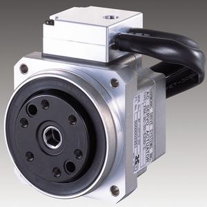
Direct-drive rotary actuators use a style of rotary servo motor that has a flat construction principle, known as a torque motor, or a pancake motor. The actuator’s table top, where the load is attached, is directly mounted to the motor, so components that would introduce compliance and backlash — such as couplings, screws, or belts — are eliminated. This gives direct-drive versions very high positioning accuracy, repeatability, and stiffness.
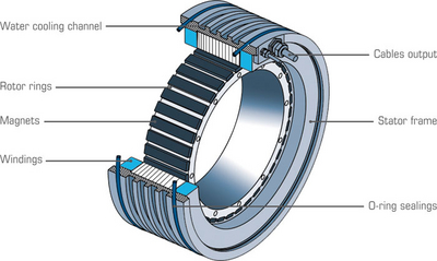
Image credit: ETEL S.A.
Rotary actuators — particularly direct-drive versions — are often used as the rotary axis in multi-axis systems such as Cartesian and gantry robots. And because electrical rotary actuators provide tight control over speed and positioning accuracy, they’re often chosen over pneumatic and hydraulic designs in printing, machining, assembly, and inspection applications.
Continuous versus fixed rotation
Another permutation of the rotary actuator is the rotary indexing table. In general, rotary actuators are used for moving loads at any angle, while rotary indexing tables are designed to move loads to pre-set, fixed positions, where the load dwells for some time and then moves to the next position. For example, an indexing table would be used for a part that required a machining operation to be performed around its circumference at 90 degree intervals.
As in the linear world, in the world of rotary motion, a distinction is often made between rotary actuators and a rotary stages. Rotary stages are commonly used in applications that require a very high flatness of travel during rotation — in other words, there should be no (or very little) “tilt” or “wobble” as the stage rotates. This is typically achieved by using highly-machined base and table structures with stringent requirements for flatness, along with high-precision radial bearings or crossed roller bearings. However, the distinction between rotary actuators, rotary stages, and even rotary tables is not strictly followed, so it’s not uncommon to see these terms used interchangeably.
Filed Under: Motion Control Tips