Position sensing is a critical function across a wide range of applications, from robot drive chains to conveyor belts in supply chain operations to the swaying of wind turbine towers. It can take many forms, including linear, rotary, angular, absolute, incremental, contact, and non-contact sensors. Specialized sensors have been developed that can determine positions in three dimensions. Position sensing technologies include potentiometric, inductive, eddy current, capacitive, magnetostrictive, Hall effect, fiber optic, optical and ultrasonic.
This FAQ briefly presents the various forms of position sensing and then reviews an array of technologies that designers can select from when implementing a position sensing solution.
There are numerous factors to consider when selecting position sensors. Some examples include:
- Position measurements can be linear, rotary, or angular and can be static or dynamic (measuring speed and/or acceleration).
- Linear sensors are typically limited to a specific measurement range, while rotary sensors usually provide measurements in terms of revolutions or degrees.
- These sensors can be based on contact or non-contact technologies. Contact sensors are often less expensive, while non-contact sensors tend to be more reliable.
- A resolver is a specialized non-contact rotary sensor that can provide both position and velocity feedback.
- Some sensors only provide incremental measurements from one point to another, while others provide absolute position information relative to a specific reference point.
Potentiometric position sensors
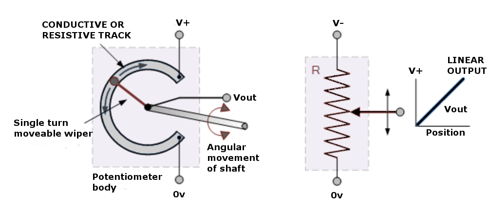
Potentiometric position sensors are resistance-based devices that combine a stationary resistive track with a wiper attached to the object whose position needs to be sensed. Movement of the object moves the wiper along the track. The object’s position is measured with a fixed dc voltage using the track and wiper to form a voltage divider network to measure either linear or rotary motion (Figure 1). Potentiometric sensors are low cost but typically have low accuracy and repeatability.
Inductive position sensors
Inductive position sensors use changes in the characteristics of a magnetic field that is induced in the coils of the sensor. Depending on their architecture, they can measure linear or rotary positions. A linear variable differential transformer (LVDT) position sensor uses three coils wound on a hollow tube; a primary coil and two secondary coils. The coils are connected in series with the phase relationship of the secondary coils 180° out of phase with respect to the primary coil. A ferromagnetic core called the armature is placed inside the tube and is connected to the object whose position is being measured. An excitation voltage is applied to the primary coil, which induces an electromagnetic force (EMF) in the secondary coils. By measuring the voltage difference between the secondary coils, the relative position of the armature, and the object it’s attached to, can be determined. A rotary voltage differential transformer (RVDT) uses the same technology to track rotational positions. LVDT and RVDT sensors provide good accuracy, linearity, resolution, and high sensitivity. They are frictionless and can be sealed for use in harsh environments.
Eddy Current Position Sensors
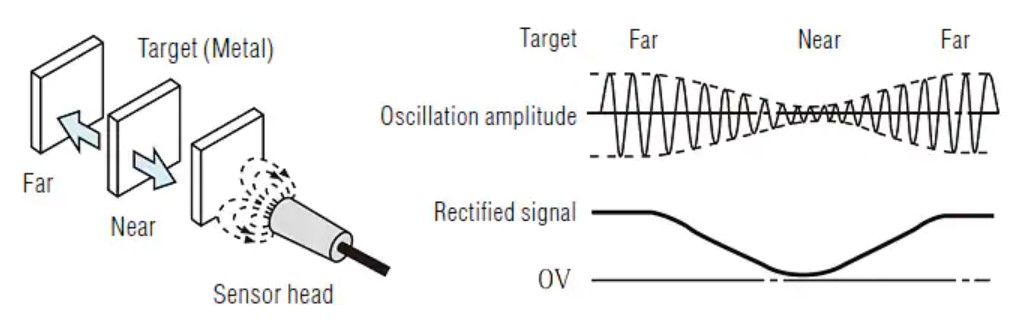
Eddy current position sensors work with electrically conductive objects. Eddy currents are induced currents that occur in a conductive material in the presence of a changing magnetic field. These currents flow in closed loops and generate a secondary magnetic field. An eddy current sensor consists of a coil and linearization circuit. An alternating current energizes the coil to generate the primary magnetic field. As the object moves closer or further away from the coil, its position can be sensed using the interaction of the secondary field generated by the eddy currents, which impacts the coil’s impedance. As the object gets closer to the coil, the eddy current loss increases, and the oscillation voltage becomes smaller (Figure 2). The oscillation voltage is rectified and processed through a linearization circuit to produce a linear dc output proportional to the object’s distance.
Eddy current devices are robust non-contact, and often used as proximity sensors. They are omnidirectional and can determine the relative distance to the object but not the direction or the absolute distance to an object.
Capacitive position sensors
As their name suggests, capacitive position sensors measure changes in capacitance to determine the position of the object being sensed. These non-contact sensors can be constructed to measure linear or rotational positions. They consist of two plates separated with a dielectric material and use one of two methods to detect the position of the object:
- Changing the dielectric constant of the capacitor
- Changing the overlapping area of the capacitor plates
To cause changes in the dielectric constant, the object whose position is to be detected is attached to the dielectric material. As the dielectric material moves, the capacitor’s effective dielectric constant changes due to the changing combination of dielectric material area and the dielectric constant of air. Alternatively, the object can be attached to one of the capacitor plates. As the object moves, the plates move closer or farther apart, and the change in capacitance is used to determine the relative position.
Capacitive sensors can measure object displacement, distance, position, and thickness. Due to their high signal stability and resolution, capacitive displacement sensors are used in laboratories as well as industrial settings. For example, capacitive sensors are used to measure film thickness and the application of the adhesive in automated processes. In industrial machines, they are used to monitor displacement and tool positions.
Magnetostrictive position sensors
Magnetostriction is a property of ferromagnetic materials that causes the material to change its size or shape in the presence of an applied magnetic field. In a magnetostrictive position sensor, a moveable position magnet is attached to the object being measured. It includes a waveguide, which consists of a wire through which a current pulse is transmitted, connected to a sensor located at the end of the waveguide (Figure 3). When a current pulse is sent down the waveguide, a magnetic field is created in the wire that interacts with the axial magnetic field of the permanent magnet (magnet in cylinder piston, in Figure 3a). The field interaction results from a twisting (the Wiedemann effect) that causes a strain in the wire, generating a sonic pulse that travels along the waveguide and is detected by the sensor at the end of the waveguide (Figure 3b). By measuring the elapsed time between the current pulse’s initiation and the sonic pulse’s detection, the relative location of the position magnet and, therefore, the object can be measured (Figure 3c).

Magnetostrictive position sensors are non-contact sensors and are used to detect linear position. The waveguide is usually housed in a stainless steel or aluminum tube, enabling these sensors to be used in dirty or humid environments.
Hall Effect position sensors
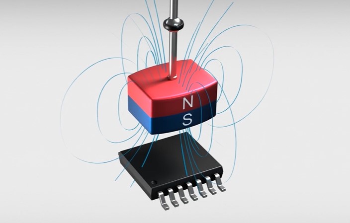
When a thin, flat conductor is placed in a magnetic field, any current flowing tends to accumulate on one side of the conductor, resulting in a potential difference called the Hall voltage. If the current in the conductor is constant, the magnitude of the Hall voltage will reflect the strength of the magnetic field. In a Hall effect position sensor, an object is connected to a magnet housed in the sensor shaft. As the object moves, the position of the magnet changes relative to the Hall element, generating a varying Hall voltage. By measuring the Hall voltage, the object’s position can be determined. Specialized Hall effect position sensors are available that can determine positions in three dimensions (Figure 4). Hall effect position sensors are non-contact devices that provide high reliability and fast sensing and can operate over wide temperature ranges. They are used across a range of consumer, industrial, automotive, and medical applications.
Fiber-optic position sensors
There are two basic types of fiber optic sensors. In intrinsic fiber optic sensors, the optical fiber is used as the sensing element. In extrinsic fiber optical sensors, the optical fiber is combined with another sensor technology to relay signals to remote electronics for processing. In the case of intrinsic fiber optic position measurements, the time delay can be determined using a device such as an optical time-domain reflectometer. The wavelength shift can be calculated using an instrument implementing optical frequency domain reflectometry. Fiber-optic sensors are immune to electromagnetic interference, can be designed to operate in high temperatures, and do not conduct electricity so that they can be used in proximity to high voltages or flammable materials.
Another type of fiber optic sensing based on Fiber Bragg grating (FBG) technology can also be used for position measurements. An FBG acts as a notch filter that reflects a narrow portion of light centered around the Bragg wavelength (λB) when illuminated by a broad spectrum of light. It’s fabricated as a microstructure inscribed into the core of an optical fiber. FBGs can be fabricated to measure various parameters such as temperature, strain, pressure, tilt, displacement, acceleration, and load.
Optical position sensors
There are two types of optical position sensors, also called optical encoders. In one case, light is sent to a receiver at the other end of the sensor. In the second type, the emitted light signal is reflected from the monitored object and returned to the light source. Depending on the sensor design, a change in the light characteristics, such as wavelength, intensity, phase, or polarization, is used to determine the object’s position. Encoder-based optical position sensors are available for both linear and rotational movement. These sensors fall into three primary categories; transmissive optical encoders, reflective optical encoders, and interferential optical encoders.
Ultrasonic position sensors
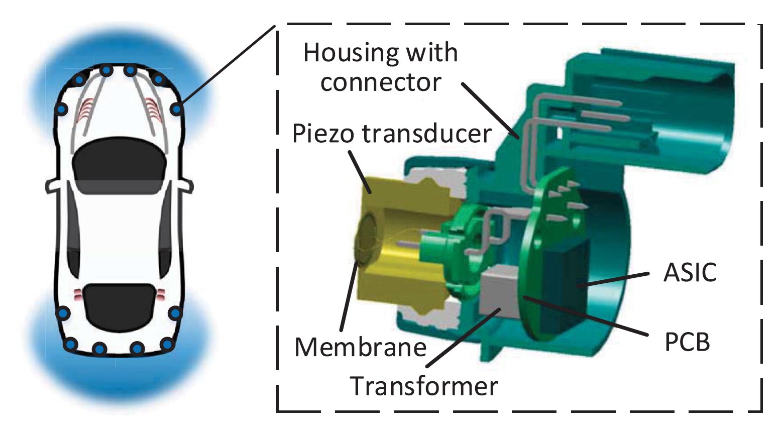
Ultrasonic position sensors use a piezoelectric crystal transducer to emit a high-frequency, ultrasonic sound wave. The sensor measures the reflected sound. Ultrasonic sensors can be used as simple proximity sensors, or more sophisticated designs can provide ranging information. Ultrasonic position sensors work with target objects of various materials and surface characteristics and can detect small objects over a larger distance than many other types of position sensors. They resist vibration, ambient noise, infrared radiation, and electromagnetic interference. Examples of applications using ultrasonic position sensors include liquid level detection, high-speed counting of objects, robotics navigation systems, and automotive sensing. A typical automotive ultrasonic sensor consists of a plastic housing, a piezoelectric transducer with an attached membrane, and a printed circuit board with the electronic circuitry and microcontroller to transmit, receive, and process the signals (Figure 5).
Summary
Position sensors are available that can measure the absolute or relative linear, rotary and angular movement of objects. Position sensors can measure the motion of devices such as actuators or motors. They are also used on mobile platforms such as robots and automobiles. A wide variety of technologies are used in position sensors that have various combinations of environmental ruggedness, cost, precision, repeatability, and other attributes.
References
3D Magnetic Position Sensors, Allegro Microsystems
Analyzing and Enhancing the Security of Ultrasonic Sensors for Autonomous Vehicles, IEEE Internet of Things Journal
How to select a position sensor, Cambridge Integrated Circuits
Position sensor types, Ixthus Instrumentation
What is an inductive displacement sensor?, Keyence
What is Magnetostrictive Position Sensing?, Ametek
Filed Under: Sensor Tips