Design World

  • Home
  • Technologies
    • 3D CAD
    • Electronics • electrical
    • Fastening & Joining
    • Factory automation
    • Linear Motion
    • Motion Control
    • Test & Measurement
    • Sensors
    • Fluid power
  • Learn
    • Ebooks / Tech Tips
    • Engineering Week
    • Future of Design Engineering
    • MC² Motion Control Classrooms
    • Podcasts
    • Videos
    • Webinars
  • LEAP AWARDS
  • Leadership
    • 2022 Voting
    • 2021 Winners
  • Design Guide Library
  • Resources
    • 3D Cad Models
      • PARTsolutions
      • TraceParts
    • Digital Issues
      • Design World
      • EE World
    • Women in Engineering
  • Supplier Listings

What do the belt section designations H, J, K, L, and M mean for ribbed V-belts?

By Danielle Collins | January 6, 2022

Share

V-belts rely on friction caused by the “wedging” of the belt between pulley flanges — together with internal fiber cords — to transmit power in a wide range of industrial and consumer-goods applications. One variation of the traditional V-belt is the ribbed V-belt — also referred to as a V-ribbed, poly V, or serpentine belt.

Ribbed V-belts take the classic V-belt profile and add V-shaped ribs that run the length of the belt, in the direction of travel. (Note that this is in contrast to a synchronous, or toothed, belt, which has teeth that run crosswise, or perpendicular to the direction of travel.)

ribbed V-belts
Like other V-belts, ribbed V-belts are constructed with a cover, tension members, and a base. But in this case, the base has ribs running along the length of the belt.
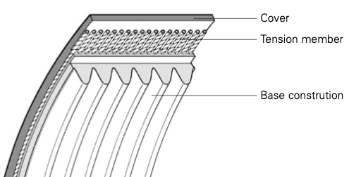
Image credit: ContiTech

Rather than relying on the wedging action between the sides of the belt and the pulley flanges, ribbed V-belts rely on frictional engagement between the ribs and the pulley, or sprocket. The ribs ensure even load distribution across the entire belt width, giving ribbed V-belts efficiencies in the range of 98 percent — similar to that of flat belts. The ribs also ensure the belt tracks properly, so alignment is less critical than for traditional V-belts and operation tends to be quieter.

The ribbed V-belt design also allows these belts to be made in thinner profiles, giving them better flexibility than other V-belts. This means ribbed V-belts can withstand high flexing frequencies and reverse bending, so they’re well-suited for applications with small pulley diameters or counter-flexing. This is why ribbed V-belts are often used in serpentine configurations. In fact, the serpentine belt found on many automobiles is a type of ribbed V-belt.

ribbed V-belts
Ribbed V-belts have efficiencies similar to flat belts and can transmit more force (power) than traditional V-belts thanks to more contact area.
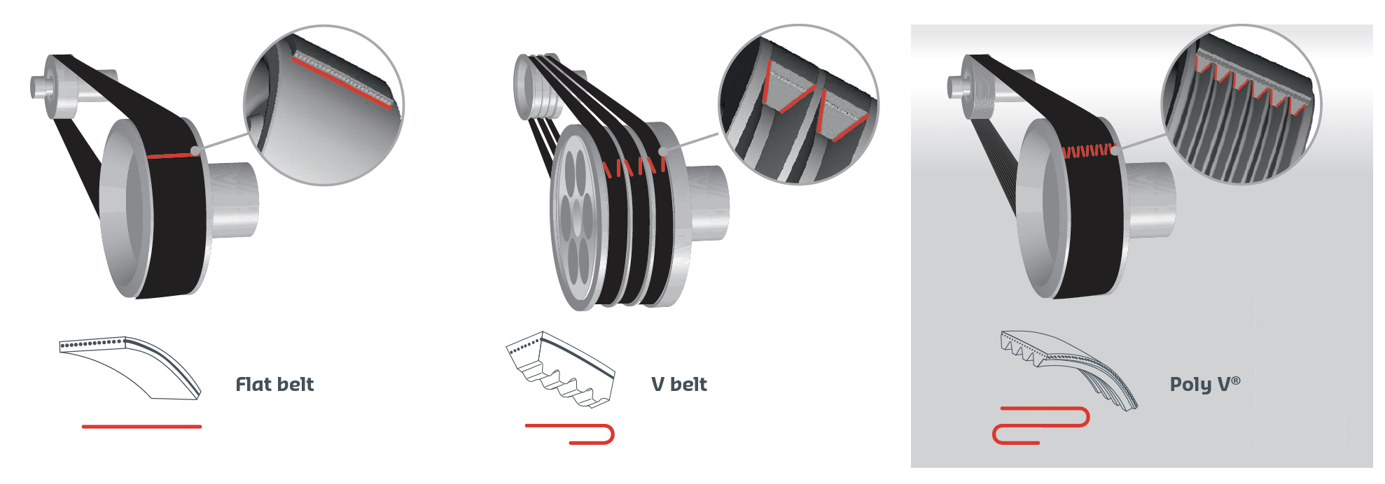
Image credit: Hutchinson
ribbed V-belts
This ribbed V-belt has seven ribs.
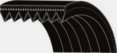
Image credit: Dura-Belt

Key information for specifying a ribbed V-belt are the belt section, number of ribs, and belt length. The belt section defines critical dimensions of the belt ribs and of the pulley, including the rib spacing (also referred to as the pitch) and the belt height. Like many V-belt designs, ribbed V-belts are available in both English and metric dimensions.

For belts manufactured in English dimensions (often referred to as “American” or “UK” belts), belt sections are designated by the letters H, J, K, L, and M. For belts manufactured in metric dimensions, the ISO 9982:2021 standard defines belt sections of PH, PJ, PK, PL, and PM. (Note that the PK belt section was originally designed for automotive applications, and the ISO 9981:2020 standard deals specifically with this profile.)

The most critical dimension specified by the belt section is the rib pitch, and each belt section is targeted for specific uses, although other applications are possible:

H (PH): 1/16 inch (1.6 mm) rib pitch— specialty applications for smaller drives

J (PJ): 3/32 inch (2.34 mm) rib pitch — fractional-horsepower applications, especially in consumer goods such as appliances and power tools

K (PK): 9/64 inch (3.56 mm) rib pitch — developed for automotive applications, especially serpentine configurations

L (PL): 3/16 inch (4.70 mm) rib pitch — industrial applications

M (PM): 3/8 inch (9.40 mm) rib pitch — high-power industrial applications such as large conveyors and agriculture equipment

Although manufacturers sometimes use their own part numbering system, most V-ribbed belts will be defined by a system that gives the number of ribs, followed by the section designation, and ending with the belt length. For example, a 7-rib, metric PK belt with a length of 2100 would be given the designation 7 PK 2100, while an English (American/UK) belt with 7 ribs, belt section K, and length of 82.7 inches would have a designation of 7 K 827 (note that length is specified in 1/10 inch increments).


Filed Under: Linear Motion Tips


Related Articles Read More >

Beckhoff optimizes linear motion with machine learning solution that eliminates cogging
PI offers new stepper motor translation stages for precision automation
Linear axis provides precision, stability for semiconductor manufacturing equipment
Lead-screw assemblies from igus for automotive applications

DESIGN GUIDE LIBRARY

“motion

Enews Sign Up

Motion Control Classroom

Design World Digital Edition

cover

Browse the most current issue of Design World and back issues in an easy to use high quality format. Clip, share and download with the leading design engineering magazine today.

EDABoard the Forum for Electronics

Top global problem solving EE forum covering Microcontrollers, DSP, Networking, Analog and Digital Design, RF, Power Electronics, PCB Routing and much more

EDABoard: Forum for electronics

Sponsored Content

  • Renishaw next-generation FORTiS™ enclosed linear encoders offer enhanced metrology and reliability for machine tools
  • WAGO’s smartDESIGNER Online Provides Seamless Progression for Projects
  • Epoxy Certified for UL 1203 Standard
  • The Importance of Industrial Cable Resistance to Chemicals and Oils
  • Optimize, streamline and increase production capacity with pallet-handling conveyor systems
  • Global supply needs drive increased manufacturing footprint development

Design World Podcasts

June 12, 2022
How to avoid over engineering a part
See More >
Engineering Exchange

The Engineering Exchange is a global educational networking community for engineers.

Connect, share, and learn today »

Design World
  • Advertising
  • About us
  • Contact
  • Manage your Design World Subscription
  • Subscribe
  • Design World Digital Network
  • Engineering White Papers
  • LEAP AWARDS

Copyright © 2022 WTWH Media LLC. All Rights Reserved. The material on this site may not be reproduced, distributed, transmitted, cached or otherwise used, except with the prior written permission of WTWH Media
Privacy Policy | Advertising | About Us

Search Design World

  • Home
  • Technologies
    • 3D CAD
    • Electronics • electrical
    • Fastening & Joining
    • Factory automation
    • Linear Motion
    • Motion Control
    • Test & Measurement
    • Sensors
    • Fluid power
  • Learn
    • Ebooks / Tech Tips
    • Engineering Week
    • Future of Design Engineering
    • MC² Motion Control Classrooms
    • Podcasts
    • Videos
    • Webinars
  • LEAP AWARDS
  • Leadership
    • 2022 Voting
    • 2021 Winners
  • Design Guide Library
  • Resources
    • 3D Cad Models
      • PARTsolutions
      • TraceParts
    • Digital Issues
      • Design World
      • EE World
    • Women in Engineering
  • Supplier Listings