Design World

  • Home
  • Technologies
    • 3D CAD
    • Electronics • electrical
    • Fastening & Joining
    • Factory automation
    • Linear Motion
    • Motion Control
    • Test & Measurement
    • Sensors
    • Fluid power
  • Learn
    • Ebooks / Tech Tips
    • Engineering Week
    • Future of Design Engineering
    • MC² Motion Control Classrooms
    • Podcasts
    • Videos
    • Webinars
  • LEAP AWARDS
  • Leadership
    • 2022 Voting
    • 2021 Winners
  • Design Guide Library
  • Resources
    • 3D Cad Models
      • PARTsolutions
      • TraceParts
    • Digital Issues
      • Design World
      • EE World
    • Women in Engineering
  • Supplier Listings

What is a 7th axis (also known as an RTU) and when is it used?

By Danielle Collins | April 15, 2021

Share

Linear Cartesian and gantry robots are used extensively in automation, particularly for tasks such as pick and place and assembly. But for applications that require movements such as changing the orientation of a part or navigating around complex obstacles, the robot of choice is often the 6-axis articulated robot.
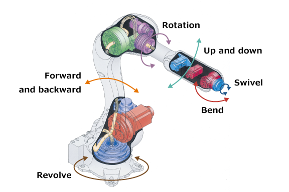
6-axis robot joints
Articulated robots use at least three rotary joints, and as the name suggests, 6-axis articulated robots use six such joints to provide six degrees of movement, from the base to the wrist.
Image credit: Kawasaki

Despite their dexterity, the reach of a 6-axis robot is closely tied to the robot’s footprint and payload, making it difficult to achieve a long reach without using a correspondingly large robot. Case in point: Typical 6-axis robots have a reach of less than 1000 mm. For longer reach, the base, or pedestal, of the robot must increase accordingly to support the mass and overhung load of the robot arm and its payload. For example, a 6-axis robot with a horizontal reach of 2000 mm might require a pedestal diameter (and, therefore, floor space for mounting) in the range of 700 mm.

This limited reach can eliminate 6-axis designs from consideration in applications where they would otherwise be an ideal solution. For example, 6-axis articulated robots are well-suited for dispensing fluids or applying tapes onto objects with complex shapes. But if the object is very large, such as an automotive windshield, the size of 6-axis robot that would be needed to reach the entire surface might be prohibitive in terms of cost and footprint. Or take the case of a drilling application that requires traversing the length of an airplane wing, requiring multiple 6-axis robots to cover the entire working area.

Although many long-stroke applications can be addressed with gantry robots, operations such as those described above also require complex movements that are difficult to achieve with an end effector on a gantry robot.

The solution for these applications is to mount the articulated robot on a robot transfer unit, which serves as a 7th axis to transport the 6-axis robot along a linear path. This extends the work envelope of the 6-axis robot and makes it possible to use one robot in applications that span long distances or multiple workstations. 

In this application, placing an articulated robot on a 7th axis allows the robot to transfer parts from a machining center to another, stationary robot.
Image credit: Mesh Automation

Robot transfer units can be pre-assembled linear actuators or they can be custom-built by an OEM or integrator to meet specific length, footprint, and rigidity requirements. Virtually any linear actuator type — belt, screw, rack and pinion, or linear motor — can serve as a 7th axis, although belts, rack and pinion drives, and linear motors are the most common options since they can provide the extremely long travel lengths typically required. And with linear motors and rack and pinion drives, multiple articulated robots can be mounted on one RTU and controlled independently.

7th axis robot
Robot transfer units can be configured to carry the articulated robot upright, suspended from above, or wall-mounted.
Image credit: Rollon

When sizing or designing a 7th axis for an articulated robot, it’s important to remember that the transfer unit must be able to withstand the dynamic forces that result from moving the robot and its payload, as well as the static (and, in some cases, additional dynamic) forces that occur when the robot carries out its intended process — drilling, welding, fastening, or dispensing, for example. The addition of a 7th axis also presents other design considerations, such as cable management and safety of other equipment and personnel, that should be addressed.

7th axis robot transfer unit
7th axis linear transfer units can also be used to transport collaborative robots (cobots).
Image credit: Universal Robots

This video from Kawasaki shows how the movements of a 6-axis articulated robot mimic human movements.


Filed Under: Linear Motion Tips


Related Articles Read More >

High-precision three-axis positioning stages feature four motor options
Programmable linear actuator features stroke to 100 mm
New I/O interface from LINAK expands features, control options
Bosch Rexroth adds high-force model to electromechanical cylinder line

DESIGN GUIDE LIBRARY

“motion

Enews Sign Up

Motion Control Classroom

Design World Digital Edition

cover

Browse the most current issue of Design World and back issues in an easy to use high quality format. Clip, share and download with the leading design engineering magazine today.

EDABoard the Forum for Electronics

Top global problem solving EE forum covering Microcontrollers, DSP, Networking, Analog and Digital Design, RF, Power Electronics, PCB Routing and much more

EDABoard: Forum for electronics

Sponsored Content

  • Global supply needs drive increased manufacturing footprint development
  • How to Increase Rotational Capacity for a Retaining Ring
  • Cordis high resolution electronic proportional pressure controls
  • WAGO’s custom designed interface wiring system making industrial applications easier
  • 10 Reasons to Specify Valve Manifolds
  • Case study: How a 3D-printed tool saved thousands of hours and dollars

Design World Podcasts

May 17, 2022
Another view on additive and the aerospace industry
See More >
Engineering Exchange

The Engineering Exchange is a global educational networking community for engineers.

Connect, share, and learn today »

Design World
  • Advertising
  • About us
  • Contact
  • Manage your Design World Subscription
  • Subscribe
  • Design World Digital Network
  • Engineering White Papers
  • LEAP AWARDS

Copyright © 2022 WTWH Media LLC. All Rights Reserved. The material on this site may not be reproduced, distributed, transmitted, cached or otherwise used, except with the prior written permission of WTWH Media
Privacy Policy | Advertising | About Us

Search Design World

  • Home
  • Technologies
    • 3D CAD
    • Electronics • electrical
    • Fastening & Joining
    • Factory automation
    • Linear Motion
    • Motion Control
    • Test & Measurement
    • Sensors
    • Fluid power
  • Learn
    • Ebooks / Tech Tips
    • Engineering Week
    • Future of Design Engineering
    • MC² Motion Control Classrooms
    • Podcasts
    • Videos
    • Webinars
  • LEAP AWARDS
  • Leadership
    • 2022 Voting
    • 2021 Winners
  • Design Guide Library
  • Resources
    • 3D Cad Models
      • PARTsolutions
      • TraceParts
    • Digital Issues
      • Design World
      • EE World
    • Women in Engineering
  • Supplier Listings