Understanding impedance in twisted-pair cables help you avoid signal problems.
A twisted pair, such as what you would find in Ethernet cables, is designed to economically transport a differential signal. It is a differential-pair interconnect, even though there are only two conductors. How do we make sense of this interconnect, especially when we want to think about its common impedance?
The secret to understanding the properties of a twisted pair as a differential interconnect is to identify the third conductor: ground. In this context, I don’t mean electrical ground. I mean ground, as in the floor.
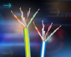
Every differential pair is composed of two single-ended transmission lines — no exceptions. Each of the two single-ended transmission lines in a twisted pair is really composed of a signal line (one of the wires in the pair) and its return path. In unshielded twisted pair cable, like Cat5 cable, the return path is a complicated structure composed of the fringe fields to the chassis, to the adjacent wires in the cable, and to any nearby conducting surface, which is usually the ground, as in the floor. This will vary as the cable is moved and the proximity to the floor or nearby metal changes.
The single-ended properties of each transmission line in a twisted pair are terrible. This is not very controlled impedance. The single-ended impedance of the cable varies down its length, depending on the position of the local conductors.
When we launch a differential signal down the two transmission lines, it is really composed of two single-ended signals propagating in the same direction. One is a positive voltage, and the other is a negative voltage. The return currents of these single-ended signals travel over a complicated and convoluted path, but generally they follow the same path. They cancel each other out because they circulate in opposite directions.
The more the return currents of the single-ended transmission lines overlap and cancel out, the less influence the convoluted return path has on the differential signal. Therefore, a twisted pair provides a very clean, uniform differential impedance.
The common signal is different. A common signal is the same voltage on both lines. The return currents of these two transmission lines overlap, but as the return currents of a common signal circulate in the same direction, they just add in the return path.
The common-impedance profile will show the impedance variation due to that convoluted return path, and it will generally be very high impedance.
The plot below shows an example of the measured differential and common impedance profile for a twisted pair, taken out of a Cat5 cable and spread over a table top.
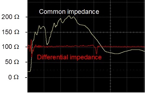
The typical common impedance of an unshielded twisted pair will vary from around 100 Ω to 200 Ω. As long as there are no common signals on the twisted pair, you don’t need to care about the common impedance. The challenge is preventing common signals from getting on the twisted pair.
Filed Under: Connector Tips

