By Jay Tedeschi
Jay Tedeschi is Sr. Community Evangelist for Autodesk Inc.

Marine
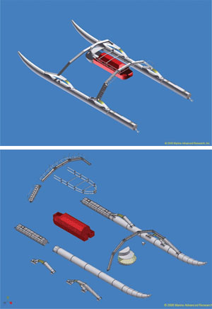
Advanced Research used digital prototyping to design this futuristic
catamaran, shown on its maiden voyage near Orcas Island, WA.
Nearly two decades have passed since Boeing used CAD/CAM to assemble a virtual model of the 777 aircraft and identify component fits and interferences. The aircraft’s design and production teams solved those problems before anything was built, and the first prototype flew without a hitch. So why did digital prototyping make news all over again with the debut of the Mercedes W204 C-Class last January?
In the years since the first 777 took flight, plenty has happened in digital prototyping. Mercedes-Benz put the automobile’s designs through a virtual 15-million-mile road course before building a physical model. The simulation represented the physical dynamics of the vehicle design in operation, from aerodynamics to braking friction.
The C-Class simulation also illustrated a subtler but important shift: the evolution of digital prototyping as an approach to design. An Aberdeen Research report (“The Digital Product Development Benchmark Report,” March 2007) confirms this shift. It found that best-in-class manufacturers—those that met their revenue, cost, launch date, and quality targets—are more likely to embrace digital prototyping.
One approach, many ways
As a practice, digital prototyping brings form and function together to solve a problem or drive innovation. The entire development team may use a simulation that represents a product’s aesthetics and function under operating conditions. It’s a logical alternative to developing each aspect of a product’s design and engineering separately.
 Digital prototyping was used to simulate and fine-tune the catamaran’s components and final assembly prior to construction. Courtesy, Marine Advanced Research. |
For example, a mechanical engineer can assess thermal properties such as heat transfer and distribution for a household iron. The constant cycle of heating, cooling and re-heating has a profound effect upon the housing and all other components mounted near the heating element, and must be taken into account when performing structural and fatigue life analysis of these components. By bringing the thermal and structural performance data together in a single digital model, the engineer can evaluate the design to determine if a certain component may fail.
Digital prototyping (DP) can be used by design teams at any time in the design cycle, from conceptual design to production. It’s a means of understanding performance and a step toward design optimization.
|
ABCs of digital prototyping According to the March 2007 Aberdeen Research benchmarking study on digital product development, best-in-class manufacturers may not even use 3D solid modeling. But they are using digital simulation. Regardless of the tools a product team uses, the practice of digital prototyping comprises these key elements: Digital communication: The Study found that top-performing manufacturers were more likely to use digital communications instead of paper-based channels between engineering and manufacturing teams. Digital pipeline: Digital communication requires more than an email system. When design and manufacturing information and feedback can be accessed electronically, teams benefit from a multi-directional flow of information. For example, engineers can tap production insights to gauge Conventions in process and even the tools used by industrial designers, engineers and manufacturing personnel can create obstacles in the digital pipeline. For example, industrial designers may develop concepts on paper, in clay, or even using task-specific software. But it’s hard to get analog—and even digital—information into a format that works with the spreadsheets or FEA software that engineers use, or the machine control programs that automate production. Functional design: Most solid-modeling software focuses on 3D geometry. That’s just one aspect of a digital prototype, and it represents intention more than actuality. Cutting-edge applications that simulate the function of 3D designs under operating conditions can bring together the aesthetics and performance aspects of a design. Teams gain insight and understanding to solve problems before they build physical prototypes. |
Marine Advanced Research used DP to simulate and fine-tune the design of a futuristic catamaran so that the boat’s frame, springs and hulls would allow the watercraft to skim across the water’s surface. Then the real catamaran charted similar results in its maiden voyage near Orcas Island, Wash. And global elevator/escalator manufacturer KONE uses DP to troubleshoot and incorporate new technology into customers’ installed systems.
There’s nothing inherently risky about integrating geometry and performance data into a single model to simulate function—unless the design team is afraid to find out that their assumptions are wrong. The value of bringing this technique into the design process sooner, rather than later, is that it helps to eliminate invalid design options and isolate those that are going to be most advantageous.
What’s more, no special tools are required. Our small-appliance engineer might use software that links thermal or fatigue analysis results to the structural simulation inputs for that iron being designed. That engineer could use any modern CAD software that supports mechanism-behavior-based assembly modeling. The principal concept of understanding form and function simultaneously doesn’t change, although the execution does.
Simulating is believing
Another way to understand the digital prototyping process is to consider the difference between 3D solid modeling and digital simulation. A solid model can be animated to indicate intended behavior, such as the rotation of an armature. While we’re willing to suspend reality when we work with these animations, the fact is that they don’t represent the design’s actual function. The engineer knows from experience that 3D design software alone doesn’t allow for modeling torque or friction data. He or she will most likely have to include some type of rules- or parameter-based approach to allow for such data in design calculations.
In contrast, a digital simulation may incorporate the calculated behavior of materials and structures under the influence of physical forces. Since it’s an approach and not a software application, digital prototyping begins with the effort to share the information that resides in different phases of product development. The industrial design, engineering design, analysis and manufacturing functions each have dedicated teams, tools and processes. Each of these core functions has the unfortunate potential to isolate information from the others. But digital prototyping eliminates this isolation.
Digital prototyping in action
To illustrate, consider the personal computer. Function, not aesthetics, is usually the manufacturer’s first order of business. There is a standard set of required components—motherboard, power supply, hard drive, graphics card and so forth—that typically are procured from suppliers. These commodity parts tend to have standard dimensions, and the mechanical and electrical engineering functions determine how those parts will fit into a chassis.
Once the chassis’s dimensions have been determined and the structural design is completed with engineering analysis and solid modeling tools, the industrial design work begins. Because so much of the chassis’s design is determined by the components, thermal analysis, for example, reveals how and where heat is produced, and where ventilation must be placed to transfer that heat away from temperature-sensitive hardware.
So the industrial designer is presented with a fair number of functional constraints on aesthetics. She also happens to use a different set of tools for her work, to render the visual, dimensional and textural aspects of a product. If she can access a solid model of the engineering team’s work, and see the data associated with that model, she can develop multiple concepts for the PC’s housing with fewer take-offs (if any), and greater accuracy.
Meanwhile, the electrical engineering team uses its own tools to design a point-to-point diagram for the wiring that connects components within the PC. Since their schematic simply represents what needs to be connected and the sequence of connections, manufacturing personnel on the shop floor have to produce a physical model, using a nail board, to model connections and determine routing and the distance between points that dictated wire lengths in the finished product. It’s a time-intensive way to arrive at a design for wiring the computer.
Many of today’s design software tools allow for the merging of that same schematic data with the spatial location of the various electrical components. These tools automate the production of not only the wire harness itself, but also the nail-board drawing used to document that harness assembly.
Technology can help or hinder collaboration. But teams benefit from shared information. Since the goal of DP is to take advantage of a comprehensive digital representation, teams can choose how far they carry this approach to design, not only in terms of applying it to an assembly or other product aspects, but also in terms of the tools they use. They might stick to 2D drawings and manual calculations, or use 3D solid modeling tools, or choose software applications that can read and use output from discipline-specific programs such as FEA analysis.
What’s it good for?
Physical prototypes let development teams test for fit, actuation, operation, instrumentation, and controls. That’s been good enough, for centuries. But conventional physical prototyping also can turn the development process into an inefficient, linear affair. A concept is sketched, the product engineered, and the physical prototype built and evaluated for issues and adjustments that are required. With each prototype failure, the process starts over again. But the electrical engineer, for example, may not have the opportunity to advise the industrial designer “out of sequence” and share insight that could help the designers avoid spending time on a fruitless undertaking.
The goal of digital prototyping is to bring all geometry and functional characteristics into a single model. So DP is an approach that favors a two-way pipeline over the conventional, linear sequence. Information flows to and from that model during the industrial design, engineering and manufacturing teams’ work.
The limits of digital prototyping
As much as it can do to enhance product development, digital prototyping has its limits. A virtual simulation will show how a design is likely to perform, but it won’t make choices for the development team. It can show the stresses to which a bicycle frame is exposed, but those stresses may be perfectly acceptable, and well within the structural limits of the materials used for that frame. What digital prototyping won’t show is the context for product development, such as consumer demand or business goals. In other words, development teams still have to do the work of design. They have to factor in considerations and decisions that they make with business executives, customers and suppliers. Design cycles and productivity may—or may not—fall and rise, respectively. That’s because companies that use digital prototyping to solve design problems may choose to explore more design options and produce more design iterations.
What they generally won’t do is produce more physical prototypes. According to Aberdeen, that’s a hallmark of best-in-class manufacturers. The research firm found that average performers produced 2.9 physical prototypes, while top performers built 1.5 and saved an average of 45 days and $15,000 on very complex product development. Clearly, the practice of digital prototyping is also a model strategy for good business.
|
Six steps to digital prototyping
1. The industrial designer opens the printed wiring board, keypad and display assembly, which has been created by the mechanical and electrical design teams. Concept sketches for the housing design are then created around data within the industrial design application.
2. The team agrees on the device’s aesthetics and the housing design is finalized.
3,4. The decision to switch to a full keypad mounted below a sliding display/cover triggers a redesign of the keypad membrane and printed wiring board. Model data from the industrial design tool is opened in the mechanical design software, where it is used to define the final shape of the keypad membrane assembly, as well as all supporting circuitry.
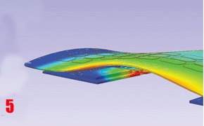
5. By performing thermal analysis, the team confirms that radiated heat, generated inside the housing will not interfere with the device’s proper functioning.
6. Finally, functional and aesthetic data are compiled in a single simulation of the finished product.
|
Autodesk, Inc.
www.usa.autodesk.com/digitalprototyping
: Design World :
Filed Under: Software • 3D CAD, Digital manufacturing, Software • CAM, ENGINEERING SOFTWARE


Tell Us What You Think!