by Jim Lamberson, Embedded Measurement and Control, Solutions Developer
A watchdog timer is an electronic circuit that initiates corrective action in response to a computer hardware malfunction or program error. It is an essential component of systems that are difficult or impossible to physically access because it provides a way to automatically recover from transient faults.
Every watchdog timer, however simple or sophisticated, must initiate two corrective actions. First, it must set the computer’s control outputs to safe levels so that potentially dangerous devices such as motors and heaters will not pose threats to people or equipment. This is a high priority action that must occur as soon as a fault is detected. After setting the outputs to safe levels, the next order of business is to restore normal system operation. This can be as simple as restarting the computer, as if a human operator has pressed the computer’s reset pushbutton, or it may involve a sequence of actions that ultimately ends with a computer restart. Also, a watchdog timer can respond to faults more quickly than a human operator, making it invaluable in cases where a human operator would be too slow to react to a fault condition. Watchdog timers are widely used in embedded and remote systems, in equipment ranging from microwave ovens to Mars rovers.
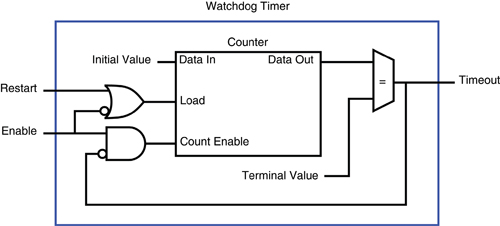
Watchdog timers consists of a digital counter that counts from an initial value to a terminal value at a rate determined by a fixed-frequency clock.
Structure and operation
In general, a watchdog timer (or just “watchdog”) consists of a digital counter that counts from an initial value to a terminal value at a rate determined by a fixed-frequency clock. Typically the counter counts down from the initial value to zero, and the initial value is programmable so that the program can configure how long it takes to count to zero. The watchdog will “timeout” when the counter reaches zero, causing it to assert its timeout signal and halt counting. The timeout signal is connected to external circuitry so that it can initiate corrective action.
A program can restart the timer at any time by loading the initial value into the counter; this is commonly called “kicking” the watchdog. The watchdog is kicked by momentarily asserting its restart input (usually by writing to a watchdog control register). During normal operation, the application program regularly kicks the timer to keep it from reaching zero, typically as part of a control loop. If a fault condition prevents the program from kicking the timer, then the watchdog will timeout and initiate corrective action.
Some watchdogs can be enabled and disabled by software, making it possible for a program to enable the watchdog only when its services are needed. Other watchdogs are automatically enabled upon system boot and cannot be disabled at all; these are typically used to detect and recover from boot faults. In some cases, a computer may employ both types of watchdogs. In theory, there is no upper limit to the number of watchdogs used in a computer.
Software-enabled watchdogs are typically disabled upon system reset. When a control program starts executing, it enables its watchdog before it starts to control the output signals. Once the watchdog is enabled, the program must regularly kick the watchdog to prevent timeouts. When the application is preparing to terminate, it sets all outputs to safe states and ceases output control before disabling the watchdog; the application can terminate after disabling the watchdog.
Watchdog architectures
Three watchdog architectures are discussed here, each with progressively greater complexity and capabilities. The first is a simple, single-stage watchdog that unconditionally triggers a system reset. Next is a two-stage watchdog that provides an opportunity for program-managed recovery. Finally, a three-stage watchdog is described that allows for program-managed recovery and, failing that, it provides an opportunity to log debug information.
Simple watchdog
The most basic watchdog circuit has a single timer that invokes an immediate computer restart upon timeout. The timeout signal is connected to the computer’s system reset input, either directly or through a conditioning circuit, so that a computer restart will occur when the watchdog times out. This architecture depends on the system reset to force control outputs to their safe states. Some computers will power-down if a continuous timeout signal is applied to the system reset input. In such cases, a pulse may be required to initiate a system restart. A pulse generator can often be used to satisfy this requirement.
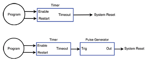
A simple watchdog has a single timer that invokes an immediate computer restart upon timeout.
Fail-safe systems in multistage watchdogs
It’s been emphasized that a watchdog timeout must cause the computer’s control outputs to promptly switch to safe states. This will happen automatically if the watchdog triggers an immediate computer restart (as in the previous example). However, a multistage watchdog timeout doesn’t immediately restart the computer; it merely schedules a restart to occur at a future time. Consequently, a multistage watchdog must work in concert with special circuitry that will switch outputs to safe states upon timeout, prior to the computer restart.
One way to do this is to employ a dedicated control reset signal that resets the control circuitry (but not the computer) upon watchdog timeout. This is easily implemented but it presents some complications and shortcomings. For example, a control reset will restore outputs to their default power-up states, but the default states may be sub-optimal safe states, and the ideal safe states may even change as a function of the overall system state. Also, a reset can cause the loss of important state information needed for fault recovery, and it may interfere with the operation of interfaces that could otherwise continue to function normally during a fault condition.
Use a dedicated control reset signal that resets the control circuitry (but not the computer) upon watchdog timeout.
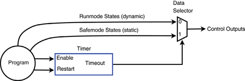
A superior alternative is to define two different sets of control states, “Runmode” and “Safemode,” and employ a data selector to route the state sets to the outputs under watchdog control. The program can modify Runmode states at any time, but it can change Safemode states only when permitted by a special write-protect mechanism. Typically, the program will begin to control the Runmode states after it establishes Safemode states, which comprise a complete, customized set of safe states for all outputs.
During normal operation, the Runmode states are routed through the data selector to the outputs. Upon watchdog timeout, the data selector switches input sets so that Safemode states are applied to the outputs in place of Runmode states. Since the control circuitry has not been reset, it will continue to function normally (to the extent possible) and it will retain interface state information (e.g., incremental encoder counts, captured events, hardware configuration) that may be needed for fault recovery.
Two-stage Watchdog
An abrupt system restart can be very expensive in terms of both downtime and loss of important state information. One or both of these costs can be mitigated with a multistage watchdog. This two-stage watchdog immediately switches the control outputs to safe states, but instead of triggering an immediate system restart, it schedules a deferred system restart and signals the computer, thus allowing time for the program to attempt to recover from the fault or log state information. If the program successfully recovers, the scheduled system reset will be canceled and the system will have avoided an expensive restart.
This two-stage watchdog immediately switches the control outputs to safe states.
During normal operation, the program kicks Timer1 at regular intervals to prevent it from timing out. As long as Timer1 has not timed out, Timer2 is disabled and held at its initial value, and the control outputs are allowed to change under program control.
If a fault causes Timer1 to timeout, its Timeout signal will simultaneously switch the outputs to safe states, start Timer2 running, and request interrupt service. If the computer is able to respond to the IRQ, then the program will have an opportunity to try to recover from the fault condition or, if the fault is uncorrectable, then the program can save state and fault information. Upon successful recovery, the program will disable Timer1 (and by extension, Timer2), thus canceling the system reset. If the computer can’t respond to the IRQ or recovery is impossible, a system reset will be invoked when Timer2 times out.
If the program will never take advantage of the IRQ, Timer1’s timeout signal can be routed to the computer’s NMI (nonmaskable interrupt) input instead of a maskable IRQ input. In this case, a NMI notifies the computer that a system restart is imminent, and Timer2 will give it time to record fault information before the restart is triggered.
Three-stage Watchdog
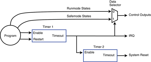
This multistage watchdog extends the two-stage watchdog by adding a third timer, making it possible to record debug information if graceful recovery fails.
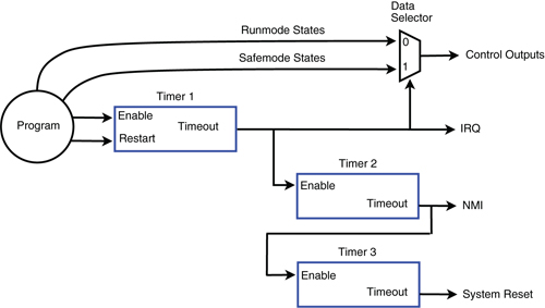
This multistage watchdog extends the two-stage watchdog by adding a third timer.
During normal operation, the program kicks Timer1 at regular intervals to prevent a timeout. While Timer1 is running, Timer2 and Timer3 are disabled and held at their initial values and the control outputs are allowed to change under program control. As in the previous example, a Timer1 timeout will switch the outputs to safe states, start Timer2, and requests interrupt service. If the computer is able to respond to the IRQ, the program will attempt to recover from the fault condition and, if successful, the program will disable Timer1 (and by extension, Timer2), thus canceling further corrective actions.
If the computer cannot respond to the IRQ, or it takes too long to respond, or graceful recovery is impossible, Timer2 will timeout, which in turn will start Timer3 and assert a non-maskable interrupt request to indicate that a system restart is imminent. If the computer is appropriately configured and able to respond to the NMI, it will do so by logging important fault information (e.g., crash dump). The system will restart when Timer3 times out.
Sensoray
www.Sensoray.com
Filed Under: ELECTRONICS • ELECTRICAL


This was helpful..thanks. It could be useful in a project I’m working on now. Is a watchdog/safemode combo available somewhere or do I have to make it myself?