Getting your motor and drive to play nice together doesn’t have to be a mystery. Here are some of the most common problems and the quick solutions to get these two critical components working together.

Using shielded cabling whenever possible can help eliminate noise issues in drive applications.
Application engineers are often the ones on the front lines of the interaction between a company’s products and its customers. As such, they often get to field the questions about how a product works and, perhaps more than we’d like to, why something doesn’t work.
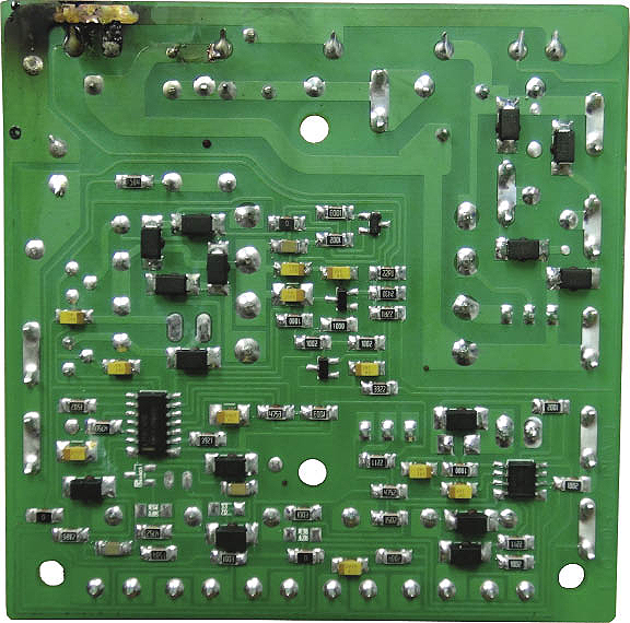
A damaged drive with a blown SCR (upper left corner) caused by an excess of current. Possible causes could include a short on the motor output, grounding on the motor terminals, or an overloaded motor, among other causes.
With drives and motors, there are a few common problems that application engineers tend to see the most. Below is an overview of the most common problems and the fixes to get your drive and motor working properly.
Drive doesn’t run the motor
This is one of the questions we’re most frequently asked. While a bad drive is certainly a possibility, there are several things you can do to insure you’re looking in the right place for the root cause of the problem.
• Line power: Make sure the drive is actually receiving power. The best way to accomplish this is to measure the supply voltage as close as possible to the drive, ideally right at the power input terminals.
• Proper connection of motor: If the motor leads aren’t connected directly to the drive terminals, any device external to the output of the drive can be a potential suspect. Most DC motors have an armature resistance in the 10s of ohms or less. Measure the motor resistance right at the drive. If the measurement shows an open (high ohm value), the problem is not the drive. Check motor relays, plugs, connectors, conduit boxes, etc.
• Make sure the motor is receiving a signal: Measure the voltage at the drive’s output terminals. If there’s a voltage present, then the drive is telling the motor to rotate. If the motor is not moving, then there is something wrong in the motor wiring or with the motor itself.
• Control signal: Make sure the drive is actually receiving a command signal to make the motor run. If using a speed potentiometer, measure across the CCW terminal and the center terminal to see if there is a linear increase or decrease in the command signal as you vary the position of the potentiometer. If an external command signal is being provided, make sure it varies in the way you’d expect.
• Enable/Inhibit: Some applications may use inhibit or enable commands. Make sure the drive is not being commanded to not put out motor voltage. Most drives have Inhibit terminals and some also have Enable terminals.
• Trim pot adjustments: Some adjustments on the drive can cause motor voltage not to be present. A Current Limit pot when set too far CCW can cause the motor to stall as soon as it demands current.
• Input Voltage Selector Switches: While many drives have auto ranging power supplies, some drives may require you to setup the drive to accept either 115VAC or 230VAC.

Drive keeps blowing fuses/tripping breakers
A defective drive can definitely cause fuses or breakers to trip. Since the drive conducts the same amount of current as the motor, it’s one of the most stressed components of a drive system. In most cases, drives don’t simply go bad but rather are stressed to the point of failure. Locating the source of the stress is the key to correcting the problem.
• Grounded motor: Check to make sure the motor hasn’t become grounded by checking the resistance from each terminal of the motor to earth ground. If using an ohmmeter, the resistance to ground should be millions of ohms or essentially an open. A motor’s internals can either permanently or momentarily short to the case. A grounded motor will almost instantly cause permanent drive damage, giving the false impression that the drive is the source of the problem.
• Line Power: Make sure that the line power is clean. Certain drives are more susceptible to problems caused by “dirty” line voltage as they may use certain portions of the 60Hz line as a clock. Line power can be distorted by the cycling of large machines, motors, pumps or welding operations. AC line filters can help maintain a clean AC waveform.
• Wiring: If using a field or shunt wound motor, connecting the armature winding of the motor to the field output of the drive will permanently damage the drive and give the false impression that the drive is the problem. Even if the motor is disconnected, a damaged drive will continue to blow fuses or trip breakers.
• Speed command signal: If using an external command signal to control motor speed, make sure the signal is isolated or make sure the drive has input isolation. Connecting two non-isolated devices together will cause damage to the drive and the device providing the signal.
• Overloading: Exceeding the drive’s current rating or ambient operating temperature can stress the drive to the point of failure. Monitor motor current to make sure it’s within the level expected and doesn’t exceed the rating of the drive. If the drive is in an enclosure, adding forced air will help insure the drive is operating within the ambient rating.
• Noise issues: For instance, running a wire from the potentiometer to the drive. A wire will act as an antenna, picking up ambient noise in the form of electromagnetic interference (EMI) and radio frequency (RF) signals that can impact the drive signals. Shielded wires can help protect the potentiometer from noise. Whenever possible, keep logic level wires separate from power and motor wires.
The importance of signal isolation
In motor drive applications it’s sometimes necessary to send an analog speed command signal to a drive. In those cases it’s important to make sure that either the output of the device sending the signal, or the input of the device receiving the signal, is isolated. Having input or output isolation is an added feature and is typically noted on the data sheet of the respective device. Connecting two non-isolated devices together will cause catastrophic damage to both devices. If neither device has isolation, a stand-alone isolation module can be used.

American Control Electronics
www.americancontrolelectronics.com
::Design World::
Filed Under: Factory automation, Cables + cable management, Drives (ac) + VFDs + starters, Drives (dc), Motion control • motor controls


Overloading: Exceeding the drive’s current rating or ambient operating temperature can stress the drive to the point of failure.
Current Limitation should be in every drive as per specs, otherwise when overloaded (because of human factors, we are trying to push everything to the very/over the limits), some/all IGBT’s or whatever final power components we have will blow out because of overload/overcurrent.
will air blowing to clean a dusty motor create static energy and cause failure or blow out a drive?
Is this points are applying on all drives
Hi guys I have a stepper motor drive it is a santoni(dinema) pcb3825a, at first the drive had a no calibration problem after swarping the half bridge drivers and Bi-Directional transciever, it came back with a “ADDRESSING(NO KEY ERROR), how do i go about accessing the problem, I was told these drives are a nightmare to work with…………any help would be appreciated as I am new in this field.
am working with automatic slindin door motor and drive.
one capacitor inside the drive has blunt and i try to replace it back but still yet the motor is not working . please any idea again…
Hello, am working with motor drive 1.5kw 220v 50/60hz 3ph but they have instantly stopped running and the screen isn’t reading the frequency but only showing E.0.U.5
hi,
i have centrifuge with 220VDC motor with control board, suddenly stop running, i check incoming power got 240VAC, i check the out connection to motor both using black wire i measure any voltage no voltage showing. any help how to further check?
i have a battle with dc motor speed control panel model KBLC-240D(4771D) that not supply output current, after i change output transistor and put on power it will blow it. what is the fault?
We are having the same problem that KC stated below:
hi,
i have centrifuge with 220VDC motor with control board, suddenly stop running, i check incoming power got 240VAC, i check the out connection to motor both using black wire i measure any voltage no voltage showing. any help how to further check?
Any help is appreciated.
You covered the most important troubleshooting points. Well done!
I have a problem of my own. I am attempting a repair of a 2003 Dynamic Controls DS112K revD, but I can’t find a schematic of these unit. I have so far replaced 8 mosfets(2N0608), there were a couple of them bad, but I usually replaced them all at once, since the remaining working mosfets may have gotten stressed by having to carry the additional load, and two 1800mfd caps, whose value I increased from 35v to 50v. I checked all the other discrete components, but there are amny IC’s on these board which I really can’t tell if bad or good without the schematic; otherwise I am going to have to reverse engineer the device, an arduous task that I’d rather not do.
I really would like to salvage this Rhino controller if I can, they were very rugged and dependable and provided many years of trouble free operation.
Any help will be appreciated.