
By Jeff Kapec, Principle and Executive VP, Tanaka Kapec Design Group, Inc.
Hip surgery mallet breaks the mold, giving surgeons new ease of use. CAD is a powerful technique for creating virtual prototypes of new designs. But for some product, nothing beats a physical model, based on 3D CAD designs, to create real tools for use by real people. In design of sophisticated surgical devices, for example, the design process can be enhanced when hands-on, 3-D modeling is used in conjunction with CAD.
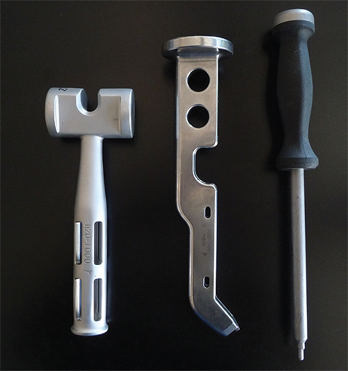
Original handles are classic orthopedic instruments, made of stainless steel and designed with focus on necessary weight and manufacturing ease.
CAD systems, for all of their advantages, cannot by themselves transform the design of some products. You can’t do better than a CAD system in creating accurate 3-D mathematical representation of a functional part. However, when designing surgical devices and many other products, how the product feels in the hand can be just as important as how it looks and functions. For example, creating a depression to guide the finger to the precise place for activating a product communicates a functional message. If this message connects to the visual aesthetics you have a win-win outcome.
At Tanaka Kapec Design Group, we have designed hundreds of medical devices and consumer products for which the feel was as important as the appearance. One project involved hip replacement surgical tools by Stryker, a leading provider of medical technology for the orthopedic industry. Stryker wanted new handle designs that could improve the performance of shaping instruments and mallets used by orthopedic surgeons in hip replacements. The previous design had been created with more consideration for the technical constraints dictated by the casting and machining process than how the product would feel in the surgeon’s hand. The predecessor handle was composed of straight lines and a simple radius, influenced more by the molding requirements and the manufacturing process. In short, it was an easy part to draw and manufacture, but it didn’t feel quite right in the hand.
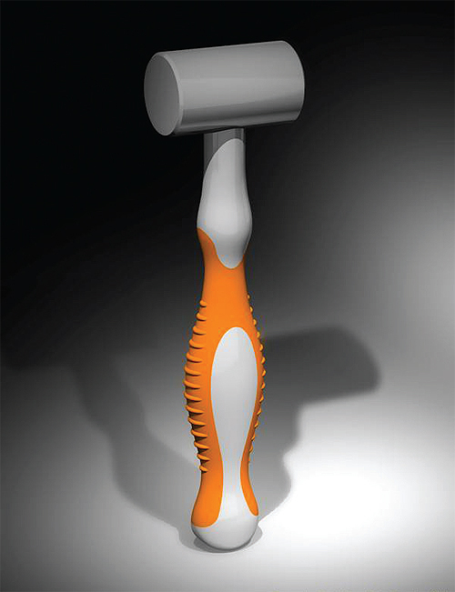
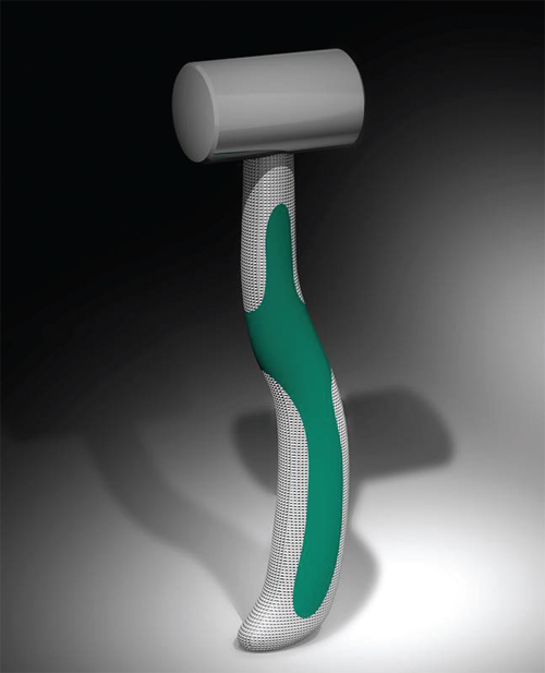
Two concepts rendered to get feedback from surgeons had a straight axis (orange handle) and an offset axis (green handle). With the offset axis, most of the weight of the mallet is set behind the impact head. The offset handlechanged the ability of the surgeon to discern how the mallet struck the surface; this approach was less favored by the surgeons once they tested impacting the implant.
We set out with CAD, then created 3-D physical models and tested them with end users. We observed the hand and body postures of more than 15 surgeons using the existing mallet in the operating room. We found that the existing mallet was being held in different positions relative to the operating table which directly corresponded to the task that had just been completed. At times the head was upside down. Other times it was parallel and at times it was at 90 degrees. At certain points in the surgery, the scrub nurse held the head of the mallet as it was being handed to the surgeon.
This operating-room observation showed that each of the tasks to be performed using the new generation tools required a different level of control and force. The new designs had to be equally suited for cleaning away materials early in the procedure, shaping and preparing the femoral canal, and gently tapping the implant into position. To meet these multiple purposes, the new handle designs would require multiple grip postures.
With this conceptual understanding, we then created 2D sketches to illustrate a series of design approaches. The next step was to create 3D physical models based on these observations and sketches. We first created a series of possible handle options out of materials we could carve and shape — 10 solid-form design concepts for evaluation by Stryker and orthopedic surgeons who would use the product.
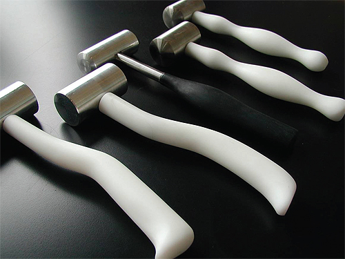
In the Stryker project, five mallet concepts were created. The center mallet with the black handle was created to learn how familiarity with a common tool like a carpenter’s hammer influenced the surgeons’ preferences.
By allowing the client and orthopedic surgeons to handle solid, sculpted physical models, we found the optimum shape for end users. Then we used CAD for engineering design to refine the model of choice and generate the mechanical engineering and design details needed for manufacturing. This approach allowed us to streamline the engineering task because all physical, emotional, tactile considerations are resolved in the industrial design phase.
The Stryker project showed that when exact dimensions translated using 3D solid modeling, an exact extrapolation was not guaranteed. The CAD system made mathematically interpreted adjustments that resulted in 1/16-in. discrepancies. Even though we couldn’t see the discrepancies, our hands told us something was different. The key project surgeon also felt a difference and commented on it before we had explained what had happened. We had to then adjust the information fed into the CAD system to compensate.
Even though 1/16-in. may not seem like much and was clearly not visible to the eye, the surgeons who tested both versions could feel the difference. This feedback validated one of our primary assumptions that in the design of many sophisticated medical tools, success is determined by touch and feel.
Discuss this on The Engineering Exchange:
Tanaka Kapec Design Group Inc.
www.tkdg.com
::Design World::
Filed Under: Software • 3D CAD, ENGINEERING SOFTWARE, Medical-device manufacture



Tell Us What You Think!