Meshing for FEA and CFD is simple: Just start with your CAD model, break it up into a bunch of small pieces, and you’re all set to go. Provided, of course, that you don’t mind getting totally bogus analysis results.
It’s more fair to say that the general concepts of meshing are simple, but that the actual practice of creating meshes that give good analysis results requires quite a bit of knowledge and experience. It’s not something you can learn from reading a short magazine article, or watching a webinar. What you can learn from an article are enough of the basic terms and concepts, so that you’ll be able to at least understand what meshing is about.
The first step in meshing is idealization of the CAD geometry. In most cases, this involves simplifying the model, removing details that are not relevant to your analysis, or that are likely to have a marginal impact on the results. It also involves cleaning-up or healing any defects in the CAD model.
Dirty CAD—models that are overcomplicated, or have defects that must be repaired, has long been one of the biggest impediments to using CAE software, particularly early in the design process, where it can do the most good. It used to be common to hear anecdotal claims that as much as 80% of the time spent on a typical CAE simulation was spent preparing and repairing the simulation model. Tools have gotten better, but the time to prepare the simulation model is still highly variable.
Once the simulation model is ready, the next step is to use it to create the mesh. In the case of FEA, the mesh is embedded within, and fitted to, the body of the simulation model. In the case of CFD, the mesh is created within the flow area defined by the body of the simulation model.
The actual mechanics to create the simulation model and the mesh will depend on whether you’re using CAD-integrated CAE software, standalone CAE software with integrated meshing, or a specialist meshing program. With CAD-integrated CAE, there’s likely to be a lot of automation, and only a few options. With standalone CAE, or with a specialist meshing program, you’ll have less automation, and a lot more control.
The end result of the process, no matter the tools used, will be a mesh made up of one or more types of geometric elements.
Types of elements
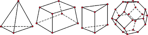
Mesh elements can be 1D (lines), or 2D (triangles, or quadrilaterals.), but most of the time, when starting with 3D CAD data, the elements will be tetrahedra (tets; 3-sided pyramids), hexahedra (hexes or bricks), polyhedra (with any number of sides), prisms, or pyramids (with 5 sides.)
If a mesh is built from hexes, it can be structured (with all elements connected in a regular addressable pattern.) Meshes composed of hexes that are not connected in a regular pattern, or of tets or polyhedra, are unstructured. It’s possible to have hybrid meshes, with a combination of both structured and unstructured elements.
Historically, hexes have been more accurate than tets, but it’s been easier to create tet-based meshes than hex-based meshes. But, at this point, it seems like no more than a generalization. The choice of element type is more often a function of the capabilities of the meshing software and the requirements of the analysis code
Making a good mesh
There’s no silver bullet that will assure you of good meshes. There are only some guidelines.
Know your physics: A good mesh must resolve the physics to be studied. It needn’t incorporate any detail in the CAD model that is not relevant to the physics. The meshing software doesn’t know the physics; it’s up to you to know it.
Things can change: Even if you spend a lot of time preparing the simulation model, refining the mesh size, and using their meshing software’s validation tools, it doesn’t mean the mesh is right for the physics problem you’re trying to simulate.
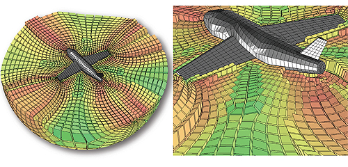
Consider, as an example, that you have good mesh for an airfoil, and it captures the flow and forces accurately. If you change the angle of attack from 0 to 45°, it’s pretty likely that you’re mesh is not still going to be good.
When you change boundary conditions, loads, or analysis type, what was a good mesh is likely to become a bad mesh. A good mesh is tuned to the needs of your problem.
Hexes are not always better than tets: It’s common wisdom that a hex mesh is better than a tet mesh. But it’s not always true anymore.
Historically, people have preferred hex meshes because, at one time, most CFD codes could only use structured meshes (or their unstructured mesh support was immature.) Also, a hex mesh uses fewer elements, and so saves memory and CPU time.
Solvers have gotten better. The accuracy difference between hex and tet meshes is not significant for most engineering problems. And any savings in resources you might gain by using a hex mesh is offset by the time saved in creating a tet mesh.
Certainly, for some applications, hex meshes have advantages (for example, where they can be aligned with flow direction.) And there are some cases where it’s standard practice to use a hybrid mesh, using structured hexes with a tet boundary layer. But there are also plenty of applications where it’s just fine to use tets.
Automatic meshing software can do a good job: Advanced meshing tools provide a high level of control, and can be very powerful—in the right hands.
If you’re an inexperienced or average user, you’re likely to get better results with automatic meshing software (assuming it’s good quality automatic meshing software) than you would trying to fiddle with all the controls on an advanced meshing program. Of course, if you’re a power user, you’re probably going to want to use advanced meshing tools, to squeeze every bit of accuracy you can out of your simulations.
Good meshes don’t need to be large: Just because you have a big computer, or a cluster, doesn’t mean you should be making meshes with massively large element counts. You need match the mesh to the physics of the system you are simulating. It only needs to be of good enough resolution to provide as accurate a result as you need for your project requirements.
Many models have symmetry. In these cases, you can often use ½ or ¼ of the full 3D CAD model, and get faster and better results. If the problem is axis-symmetric, you can get more accurate results with a 2D simulation than with 3D.
Get help: The economic payback of CAE simulation can be remarkably high. It’s worth spending the money for training.
Filed Under: Software • FEA, Software • simulation, ENGINEERING SOFTWARE


Tell Us What You Think!