Mentor Graphics couples its tools for component and system-level CFD
CFD was once the exclusive realm of analysts with deep theoretical backgrounds and extensive experience. While those analysts still rule the realm, they’re no longer alone.
The growth of early (often called “upfront” or “concurrent”) CFD tools has opened the field up to a new type of user: mechanical design engineers.
Early CFD tools are not a replacement for traditional CFD tools, or the analysts who use them. They’re optimized for ease of use and speed, embedded in CAD, and are most often used by mechanical design engineers, early in the product development process, when the cost of change is low.
The benefits of early CFD are well-established. CIMdata, the PLM industry consulting firm, has pointed out a number potential business values in early CFD:
- Faster design process
- Improved product design
- Less rework
- Improved quality
- Reduced prototypes
- Faster time-to-production
Vendors and proponents of early CFD have generally characterized these benefits in the context of component parts or assemblies. But they haven’t talked about systems.
This may be because neither early CFD tools, nor traditional CFD tools, are capable, by themselves, of modeling fluid systems. They’re both missing a critical component: 1D analysis.
1D and 3D: the fraternal twins of CFD
The CFD software that most engineers are familiar with is actually 3D CFD. It can provide detailed information on the fluid dynamics (including flow regimes, phase changes, and chemical reactions) for complex 3D components.
The CFD software that many engineers aren’t familiar with is 1D CFD. It’s used to model flow rates, pressure changes, and temperature fluctuations in one dimensional fluid systems. Essentially, networks of pipes, connectors, valves, pumps, compressors, heat exchanges, and other similar components. These kind of fluid systems are commonly found in the automotive, aviation, oil, gas, power, and energy industries.

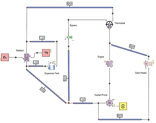
1D CFD is used to model flow rates, pressure changes, and temperature fluctuations in one dimensional fluid systems, such as this auto cooling system.
1D and 3D CFD are very different but complementary technologies. 1D CFD is used for analyzing fluid systems. 3D CFD is used for analyzing components and assemblies. While 3D CFD analysis requires starting with detailed component geometry, 1D CFD starts with a library of component models, whose characteristics have been predetermined empirically or semi-empirically. 1D CFD analysis provides an understanding of the overall behavior of a fluid system, but doesn’t provide the detailed understanding of the local behavior of individual components that could be provided by 3D CFD analysis. While 3D CFD calculations often take hours, 1D CFD calculations are relatively fast, and may only take minutes to perform.
In complex fluid systems, there are often non-standard components with complex internal flows. An ideal solution, to model systems like this, is to couple 1D and 3D CFD analysis. This action allows 1D analysis of the overall fluid system, with more detailed 3D analysis where required.
Coupling
Coupling is a somewhat standard strategy for multi-domain analysis. There are two common approaches to coupling 1D and 3D CFD. The first is co-simulation, a methodology that allows individual components to be simulated by different simulation tools running simultaneously and exchanging information in a collaborative manner.
The second is component characterization, where multiple 3D CFD analyses are used to build a response model for a component based on a range of boundary conditions. This model can then used in the 1D system model.
The choice of which approach to take is dependent on the system being analyzed. In general, if changes in the 1D model affect the 3D model, co-simulation is the right approach. If changes in either model don’t affect the other, then component characterization is a good choice.
If there is a problem with 1D-3D CFD coupling, and particularly co-simulation, it is that it’s a specialist skill. While there are some standards-based coupling tools available (for example, the MpCCI CouplingEnvironment, from Fraunhofer SCAI), the exact process required is largely dependent on the specific codes being used.
The lesson of early CFD
The benefits of early CFD come not from improved analysis capabilities, but from improved workflows compared to traditional CFD. This suggests an interesting possibility: what if 1D-3D CFD coupling could be implemented using early CFD tools, instead of traditional CFD tools, and without the services of a specialist?
Mentor Graphics has done this, recently announcing native coupling between their FloEFD Concurrent 3D CFD software and their Flowmaster 1D System CFD software.

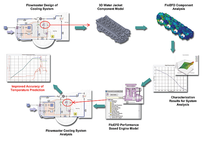
Mentor Graphics’ FloEFD CFD software uses a design of experiments to characterize the boundary conditions of complex 3D components, such as a water jacket. These data can be used in a Flowmaster system model, to predict the performance of the cooling system.
FloEFD is an outstanding example of early CFD. It is available embedded in major CAD systems (including CATIA V5, NX, Pro/E, Creo, and SolidWorks), and standalone, with tight integration to Inventor and Solid Edge. It is designed for use by mechanical design engineers, typically requiring less than 8 hours of training, and is very fast and efficient at creating analysis meshes from CAD models.
Flowmaster, which Mentor acquired earlier in the year, has been an important 1D CFD tool for about 20 years, and is used widely in the automotive, aviation, oil, gas, power, and energy industries.
The coupling workflow between FloEFD and Flowmaster is simple, and requires no programming. It starts with a systems engineer creating a fluid system model with Flowmaster, and using a lumped mass representation for the 3D component that needs to be characterized. The systems engineer passes boundary conditions from that model over to the mechanical design engineer who is designing that 3D component. The design engineer then uses those boundary conditions to create and run a design of experiments analysis for the 3D component in FloEFD, creating a response model file. The systems engineer can use the response model simply by opening the file in Flowmaster. The response model is saved in Flowmaster’s component database and can be reused later, on the same or other projects.
The coupled FloEFD/Flowmaster solution will not work for all fluid systems. There are some systems with boundary challenges that might be better served by co-simulation. (Not that this is a problem for Mentor, as Flowmaster supports co-simulation using MpCCI.) Yet, for a very large number of applications, the coupled FloEFD/Flowmaster solution will work exceptionally well, and will provide a much more efficient workflow than co-simulation.
From a business perspective, a key to reducing product development risk is having more information available, earlier in the process. Mentor’s coupled 1D-3D CFD solution provides more information, earlier in the product development process, than any comparable solution.
Mentor Graphics
www.mentor.com/mechanical
Filed Under: Software • 3D CAD, Software • FEA, Software • simulation, ENGINEERING SOFTWARE


Tell Us What You Think!