If you were going to pick a challenging use case for CFD software, you couldn’t do much better than Formula 1 racing. It’s a high-stakes game, with fast development cycles, and even faster feedback on failures. Every two weeks during the season, F1 teams get a reality check on their engineering.
As a practical matter, F1 teams don’t completely trust CFD. Not if they want to win. They use CFD as a tool to optimize their aerodynamic design before committing the money for prototypes and windtunnel testing. CFD is a force multiplier, allowing them to get to an optimal solution faster, at less cost.
In the best of all worlds, an F1 aerodynamicist would be able to take a CAD model, mesh it, run a CFD analysis, look at the results through a post-processing program, modify the CAD model, then repeat as necessary, until they get a good solution. Of course, this is not the best of all worlds: this process would simply take too long.

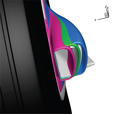
A Formula 1 brake cooling duct, showing the baseline design (gray), maximum cooling (blue), minimum drag (red), and an optimal trade-off (green.)
Consider, as an example, the optimization of a brake-cooling duct for an F1 car. John Axerio-Cilies, a PhD candidate at Stanford, along with his co-authors, recently looked at this problem.* His overarching goal was to improve the brake duct design in the presence of uncertainty, and determine the trade-off between maximizing brake cooling, and minimizing drag.
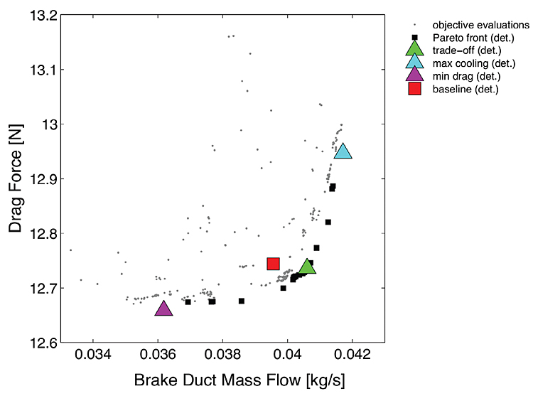
Axerio-Cilies found that, of all the areas of uncertainty considered, tire yaw angle, turbulence intensity, and contact patch width were the most significant. He found configurations of the brake duct that provided either maximum cooling or minimum drag, as well as a configuration that provided a good trade-off between these, and slightly better performance than the baseline design.
What is most interesting is how Axerio-Cilies got his results. He started with CAD geometry provided to him by Toyota Formula 1. The baseline CAD cleanup, to make the model “watertight,” took about 1 week. Creating a 30 million cell body-fitted mesh of the model took about 3 months. Running a baseline analysis, using the ANSYS Fluent solver running on 300 processors, took about 1 day.

A Pareto distribution, showing the results of CFD analyses on many variants of an F1 brake cooling duct.
Axerio-Cilies then ran several thousand analyses to understand both variability and brake-duct geometry. Using a brute force approach, this should have taken about 1,250 years for 5,000 analysis runs (a number cited in an academic paper authored by Axerio-Cilies), including re-meshing and analysis. Of course, it didn’t.
Stepping back to look at the process that Axerio-Cilies went through, it’s possible to argue that neither CAD cleanup nor meshing should have taken as long as they did. There are a number of commercial tools that can make relatively short work of repairing CAD data in preparation for meshing. There may even be some tools that can automatically (without manual intervention) create high-quality CFD meshes, without skewness, aspect ratio, warpage, or volume problems. But it’s unlikely that there are any CFD solvers available that can improve on Fluent’s performance by the degree required to do so many analysis runs in a reasonable amount of time. Even if CAD model clean-up and re-meshing were not a factor, it would still take more than 13 years to do 5,000 analysis runs on this 30 million cell model using 300 processors.
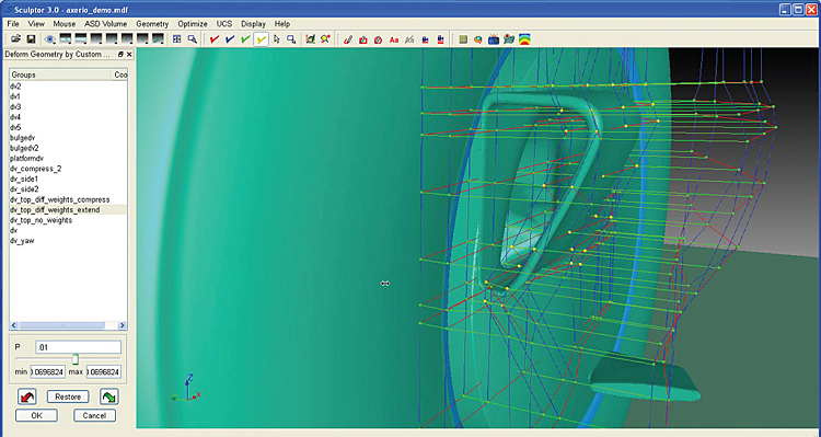
The key to reducing the solution time to an acceptable number is to not redo things that don’t need to be redone. Rather than modifying the CAD model and re-meshing, Axerio-Cilies used Sculptor, a mesh-morphing tool from Optimal Solutions.

Optimal Solutions Sculptor allows the arbitrary deformation of meshes using a matrix of control points.
Sculptor started with the baseline mesh, and, using Latin hypercube sampling (a statistical method), created a large number of variant meshes, in just a few minutes. In each of these variant meshes, only a relatively small number of cells were morphed. Most of the cells were unchanged. The result was a massive reduction in analysis time—from 1 day, down to about 2 hours per run. Using cloud computing, Axerio-Cilies was able to run thousands of analyses in only a few weeks total time.
The lesson here is pretty obvious: Your chances of finding a good solution improve if you’re able to run more analyses. If you can cut CAD model modification and re-meshing time to zero, and reduce analysis time by a factor of 12 (as Axerio-Cilies was able to), you’re going to be able to run a lot more analyses in the time you have. If you happen to be in the Formula 1 game, that could make a big impact on your ability to win on race day.
Optimal Solutions
http://gosculptor.com
ANSYS
www.ansys.com
*This research is from John Axerio-Cilies’ PhD Thesis. His co-authors include Giovanni Petrone, University of Naples, Michael Emory, Stanford, Vijay Sellappan, Enginsoft Americas, and Dr. Gianluca Iaccarino, Stanford (adviser). A recorded webinar describing this research may be found at the Optimal Solutions website, at gosculptor.com.
Filed Under: Software • 3D CAD, Automotive, Software • simulation, ENGINEERING SOFTWARE


Tell Us What You Think!