The PIGA is the oldest accelerometer and widely used in rocketry and guidance, and still the best – but MEMS-based devices are getting closer.
The previous parts looked at the principle and operation of the PIGA. This part looks briefly at its history and refinement and the MEMS-based versions of the PIGA being developed and used now.
The problem of measuring the acceleration of a moving vehicle over a wide dynamic range with fairly good accuracy and sensitivity has been known since the early 20th century, in conjunction with the associated challenge of developing a gyroscope-based IMU. However, the problem became more acute with the development of rockets in general and rockets as weapons in particular. These had very high rates of acceleration, wide acceleration dynamic range, and a need for navigation and guidance.
The V-2 PIGA
The development and refinement of the PIGA in its early years are closely linked to the German Nazi V-2 single-stage supersonic ballistic missile of World War II. Thousands of these were launched from Nazi-occupied Holland and other sites and reached England, especially London, killing thousands and causing major destruction due to its 1,000 kg (2,200 lb), which exploded on impact. The V-2 had a range of 320 km (200 mi) and a 88 km (55 mi) maximum altitude on a long-range trajectory and reached maximum supersonic speeds of 5,760 km/hr (3,580 mph).
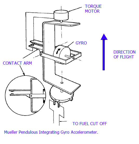
Its crude but sufficiently effective guidance system used gyroscopes to determine and correct direction and a PIGA based on an accelerometer developed by Dr. Fritz Mueller for rocket-engine cutoff (Figure 1).

This system used precision electrical contacts to actuate the torque motor and achieved an accuracy of about 600 meters over the intended flight trajectory and path. Since the number of shaft rotations represented speed, a cam switch was used to initiate missile control sequences such as engine throttle-down and shut-off (Figure 2).

Draper, who had already been deeply involved with gyroscopes and IMUs, used this PIGA as the basis for extensive refinement, culminating in IMUs which can guide an aircraft, submarine, or missile to within a few tens of meters over thousands of miles or a spacecraft to the moon and beyond. Analog electronics soon replaced many mechanical functions surrounding the orientation and PIGA gyros, then digital electronics increased precision, reduced weight, and enabled better calibration and compensation for inaccuracies.
The MEMS-based PIGA alternative
The PIGA is a very stable, linear device with very high resolution over a wide dynamic range. It is the only accelerometer to date capable at present of meeting strategic-missile thrust-axis requirements. However, they are relatively complex, large, power-hungry, and heavy and have high life-cycle costs due to the three rotating mechanisms (gas bearings, SDM ball bearings, and slip rings), among other factors.
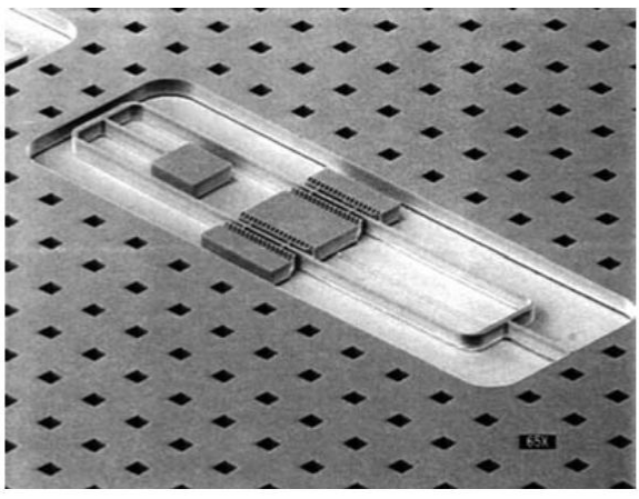
MEMS technology offers a different way to implement core accelerometer functions, and a MEMS-based PIGA offers many obvious virtues. While a rotating gyro-like mass is not viable in a MEMS design, there is a somewhat similar approach using an oscillating tuning fork in place of the rotor (Figure 3).

This replacement is the fundamental design change between the PIGA and the POGA – the pendulous oscillating gyroscopic accelerometer – and makes the device suitable for MEMS microfabrication while maintaining the fundamental physics that has produced the highest performing accelerometers.
The POGA is also a three-orthogonal-axis system. Instead of having rotating elements of the PIGA, the members are supported by flexures and designed to oscillate. The inner member is called the rotor-driven member (RDM) and generates the angular momentum just as in the PIGA. Still, instead of a fixed angular momentum, its angular momentum oscillates. The oscillating angular momentum requires an oscillating SDM to generate the gyroscopic torque that nulls the TSM.
If the RDM and SDM are forced to oscillate at the same frequency, then the equilibrium torque equation (mass m × moment arm l × acceleration) is a complicated function of the amplitude of oscillation of the RDM and the SDM, and the phase difference between their oscillations (it uses the Coriolis effect, based on vibrating mass deflection resulting from rotation). Additional trigonometric and algebraic manipulations show that acceleration is a function of the cosine of the phase difference between the two oscillations plus a second harmonic term that time averages to zero. The phase difference becomes the control signal to maintain the TSM at null in a closed-loop POGA.
The MEMS-based POGA and gyro technology have made major performance progress in the past decades. The potential benefits of this approach compared to the mechanical PIGA are very clear and significant, and the POGA performance is satisfactory for may applications. It has some shortcomings which are being addressed; for example, the bias of a MEMS gyro will wander over time due to flicker noise in the electronics and other effects. Still, significant R&D effort is going into this approach.
Conclusion
The PIGA is a clever, innovative adaptation of the well-known gyroscope to measure linear acceleration with high accuracy, precision, and range. It has been successfully used in IMUS, offering extraordinary, consistent, almost unimaginable performance levels. It has evolved from an unsavory initial application to be the core of the highest-performance IMUs used for guidance, navigation, and control over distances spanning local, regional, global, and solar-system expanses. The ongoing evolution of mechanical-based PIGAs to MEMS-based POGAs is broadening their application potential and enabling ever-smaller high-performance systems in low-power, low-weight, tiny, electronically calibrated units.
Related EE World content
Technical Articles
Inertial Measurement Units: The hidden key to Apollo success, now a MEMS device (Part 1)
Inertial Measurement Units: The hidden key to Apollo success, now a MEMS device (Part 2)
Coriolis flowmeters: A subtle global effect with local applications, Part 1: The challenge
Coriolis flowmeters, Part 2: The principle
Coriolis flowmeters, Part 3: Flowmeter design
Coriolis flowmeter, Part 4: The future
What are inertial sensors?
Gyroscopes, Part 1: Context and mechanical designs
Gyroscopes, Part 2: Optical and MEMS implementations
GPS, Part 1: Basic principles
GPS, Part 2: Implementation
Products
MEMS inertial accelerometers target spacecraft electronics testing
Tactical grade, force-rebalance SMD MEMS accelerometer includes digital interface
Gyroscope/accelerometer combo enables high-precision motion sensing
MEMS inertial accelerometer now offered in ±10 g and ±50 g ranges
Additional References
- (book) Donald MacKenzie, MIT Press, “Inventing Accuracy: A Historical Sociology of Nuclear Missile Guidance” (don’t be fooled by the odd title: this excellent book is cited by almost every other article discussing the history of inertial guidance)
- (book) Thomas Wildenberg, Naval Institute Press, “Hot Spot of Invention: Charles Stark Draper MIT and the Development of Inertial Guidance and Navigation”
- AIAA, “Inertial Instruments: Where to Now?”
- Aerospace Research Central, “The pendulous integrating gyroscope accelerometer (PIGA) from the V-2 to trident D5, the strategic instrument of choice”
- AIAA/The Charles Stark Draper Laboratory, Inc., “Inertial Instruments: Where to Now?”
- Gordon A. Thompson (MIT MS Thesis), “Inertial Measurement Unit Calibration using Full
Information Maximum Likelihood Optimal Filtering” - Wikipedia, “PIGA accelerometer”
- Kaiser and Allen, “A Micromachined Pendulous Oscillating Gyroscopic Accelerometer” or here
- AIAA/The Charles Stark Draper Laboratory, Inc., “The Silicon Oscillating Accelerometer:
A MEMS Inertial Instrument for Strategic Missile Guidance” - Journal Aerospace Lab, “Gravitation and Geodesy with Inertial Sensors, from Ground to Space”
- Military-Aerospace Electronics, “Boeing to upgrade missile guidance systems on Minuteman III land-based nuclear rockets”
- Aerospace Research Central, “Inertial Components: Past, Present, and Future”
- Draper Technology Digest, “MEMS Development at Draper Laboratory”
- David Darling, “Inertial Guidance”
- V2 Rocket History, “Technology, People, and Places”
- The V2 Rocket, “A-4/V-2 Resource Site”
- TRW/Minuteman Missile, “Minuteman Weapon System: History and Description”
- Defense World, “Boeing Wins $17M PIGA Manufacturing for ICBM Subsystem Contract”
Filed Under: Sensor Tips


