Pat Phillips • Product Manager • Fluid Power & Mechanical Products • AutomationDirect
Following these design rules will ensure a successful machine automation application.
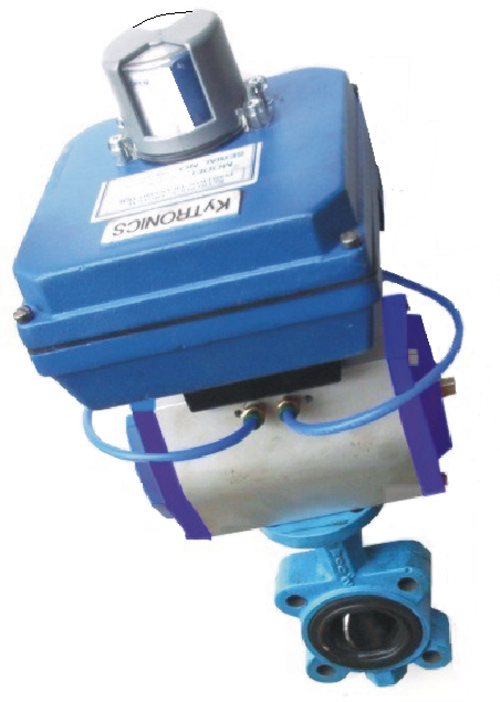
Pneumatic cylinders are a popular way to clamp, position and transfer parts in automated equipment. They also offer one of the simplest ways to achieve mechanical motion and fixturing of parts (Figure 1). However, some common problems can occur when designing and applying pneumatic actuators and cylinders—and air preparation devices such as filters, regulators and lubricators.
Design issues
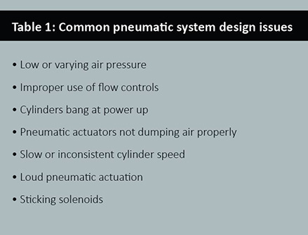
Most pneumatic system issues are caused by attempts to make a cylinder and related compressed air system components do something outside of the hardware’s design parameters. Some of the leading pneumatic system design errors are listed in Table 1 and described below.
Low or varying air pressure can negatively impact the final product and overall machine sequence. This is often caused by insufficient capacity at the air compressor, and can also be caused by undersized plant air supply tubing and piping.
Other low air-pressure problems can crop up due to operational issues involving air-driven motors and machines. For example, a manufacturing plant was experiencing low air pressure in its facility at the end of the day shift, causing one of the machines to fault due to low air pressure in its pneumatic actuation system. The problem was found to be high volume air consumers nearby, namely blow guns being used to clean machines at the end of each day.
 Lack of or improper use of flow controls can also cause pneumatic system problems. Without flow control, a cylinder may move too fast, eventually damaging the cylinder itself and/or surrounding tooling. If flow control is present but applied too vigorously, a cylinder may move too slowly to accommodate the desired high-speed operation.
Poor location of flow controls may also cause poor cylinder speed control, for example by making it too easy for an operator to change flow rates. This can be analogous to giving everyone access to a thermostat regulating building temperature, which is never a good idea. If an operator adjusts airflow for one purpose, he or she may not know it will interfere with other machine operations, such as keeping a part from jumping out of a nest.
Cylinders can bang at pneumatic system power-up if a load moves the cylinder to a retracted position when the air is shut off. Upon power-up of the pneumatic system, air can rush in and cause abrupt and possibly dangerous operation.
Another common pneumatic design issue is slow or inconsistent cylinder speed, which can lead to inconsistent stroke. This is sometimes caused by low pressure or an undersized cylinder. On the other hand, an oversized cylinder may stroke too slowly due to its large airflow requirement. Undersized valves and tubing can also restrict airflow, causing slow or erratic cylinder stroke.
Loud pneumatic actuation is typically caused by a lack of flow controls or end-of-stroke cushions, with the exhaust at the solenoid valve bank just adding to the noise. Solenoid valves can also stick in position due to contamination, and water from the air supply can block small valve passages.
Controlling pneumatic air flow
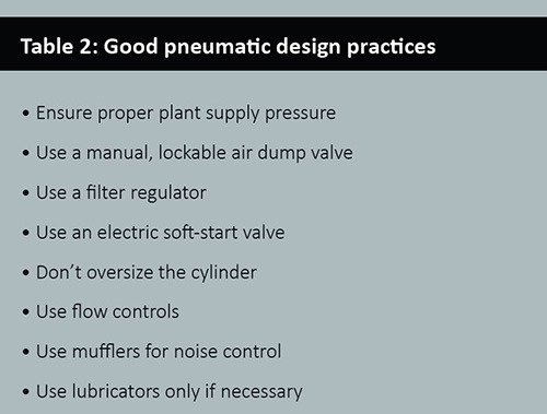
For each problem identified, certain solutions and design guidelines are available to address the issue. While the application of pneumatic cylinders can be as simple as determining the required force and speed, mechanical cylinder configuration and related pneumatic hardware must also be properly specified and installed. Design guidelines for pneumatic systems are listed in Table 2 and detailed below.
A good place to start for pneumatic design practices is to ensure adequate plant air supply pressure. Consistent plant air pressure with suitable flow allows pneumatic devices to operate as designed.
Once consistent and correct pneumatic system air pressure and flow is established, plant supply air should be connected to a manual, lockable air dump valve at each use point. This lockout, tag-out capability is important for isolating a machine—or a module of a large machine—for changeover, maintenance or tooling changes.
 A filter regulator should be installed at the air dump valve. The filter removes dust particles and water that can cause wear and operation problems for pneumatic system components. A regulator is required to throttle to the design air pressure at the use point, typically 60 to 90 psi, as the plant air supply is usually higher, about 100 to 130 psi. Operating at the design pressure as opposed to plant pressure will reduce wear on pneumatic components.
An electric, soft start valve downstream of the regulator allows air pressure to gradually increase at start-up, preventing sudden banging or slamming of cylinders at power up. This is especially important if 4-way, 2-position valves are used because a 2-position valve spool maintains its position after power off and the removal of air.
When power and air is reapplied, air will return to the cylinder. If all air was exhausted, no air is available on the other side of the cylinder. This makes speed control with flow controls non-functional. The uncontrolled speed of the cylinder could cause a high-speed stroke, commonly ending with a bang. When soft start valves are correctly applied, a machine will typically return to its home position slowly and smoothly at power up.
To avoid injury to an operator or maintenance personnel, all air must be dumped from the cylinders during machine maintenance or changeover, and the pneumatic supply must be locked off and tagged out.
A cylinder should be properly sized for the application. It’s wrong to assume bigger is better, as in many cases, machine operation won’t improve with an oversized cylinder. A cylinder that is much larger than required wastes money up front due to its higher cost, and every day thereafter because it consumes more air.
Even when a cylinder is sized properly, it may stroke too fast and require use of a flow control, typically by controlling flow of air leaving the cylinder. This also reduces noise problems caused by cylinders banging and reduces rapid exhaust racket. These flow controls are typically mounted directly to the cylinder, but can also be mounted inline near the cylinder, or at the valve if the hose between the valve and cylinder is less than about 3 ft.
Specifying cylinders with built-in cushions can help provide long-term performance in high-speed pneumatic motion applications. The cushions allow a cylinder to stroke at high speed and only slow down near the end of stroke for a quiet, low-impact stop. Adjustable pneumatic cushions are often the best solution, comprised of specially designed end caps with built-in flow controls. Mufflers can also be used to quiet cylinder or valve exhaust noise, and they are often a simple and low cost solution.
Lubricators should be used sparingly and only when necessary. Most modern pneumatic components come lubricated from the factory and do not need oil. Although not necessary for most pneumatic devices, pneumatic motors on air tools and other equipment always require a lubricator.

Air control in action
A well-designed pneumatic application starts with consistent air pressure where the plant’s compressed air system connects to the equipment or the machine.
Pneumatic pick-and-place is a common pneumatic application. A typical use for this function might be transferring items from one conveyor belt to another. Unlike a more sophisticated unit that uses servomotors, a pneumatic-powered unit can only repeat a sequence of operations to hard-stop locations. Although limited in flexibility as compared to a servo system, a pneumatic unit is less expensive by a wide margin, and is much simpler to implement and maintain.
This system should start with a good air prep setup including a locking air dump valve, an air filter, a pressure regulator and an electrically operated soft start valve (Figure 2). Air from the air prep assembly will feed into a bank of solenoid valves.
A good choice for this application would be a 5-way, 3-position, center-exhaust valve. The air should always be dumped when an emergency stop is pressed, releasing all trapped air that could cause an operator to be pinched. With a 5-way, 3-position valve, the center-off position dumps air to both sides of the cylinder. Also, resetting the emergency stop won’t cause motion until cycle start is pressed.
One valve with two 24-Vdc solenoids controls each cylinder. The off (center) condition of each valve dumps air from the cylinders. Energizing individual solenoids extends or retracts its corresponding cylinder. Sometimes to protect tooling, an anti-drop check valve is mounted to the cylinder; this can be used to prevent the cylinder from dropping due to gravity when air is dumped. However, never trap air where an operator may be pinched or crushed. Using a modular valve bank allows one common exhaust port for the system, and a good quality muffler on the exhaust port reduces noise.
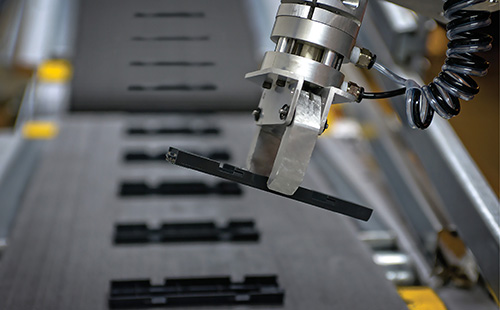
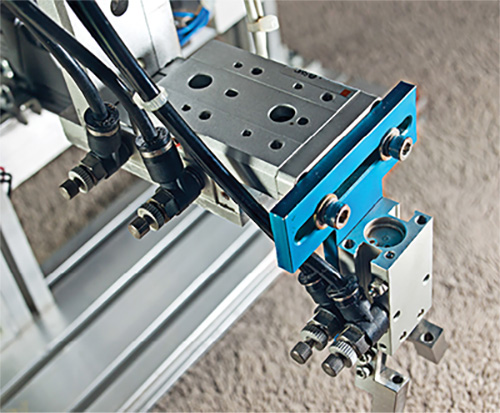
Common cylinders used in pick-and-place applications are guided rod or twin rod cylinders (Figure 3). These cylinders typically have rectangular bodies, and a fixed plate on the end of the piston rod that does not allow any rotation of the load. A basic system might travel in the X and Z directions, with some type of gripper to pick up the items. Adding a third cylinder allows travel along all three axes.
When cylinders are integrated into automated equipment and the overall machine sequence, as is often the case in pick-and-place applications, cylinder speed can become important for proper product handling. Most cylinders should include flow controls to both ports, which the exhaust air regulates as it leaves the cylinder, rather than the supply air.
Cylinder position switches are also extremely helpful to avoid beginning the stroke of one cylinder before the previous cylinder’s stroke is complete. Using timers to control a sequence instead of position sensors should be avoided in this and most cases. One stuck or slow cylinder during an automated sequence can cause a machine crash, costing much more than the cost of buying, installing and programming end-of-stroke sensors.
When it comes to pneumatic system design, watch out for the common issues, and be sure to supply, prep and distribute the air properly. When properly applied, your pneumatic devices and actuators will have a long life with limited operational issues along the way, and with minimal required maintenance.
AutomationDirect
automationdirect.com
![]()
Filed Under: Actuators, Filters (mechanical) for air + fans, Pneumatic Tips