When CADCAMNet surveyed how 3D data is used, they found that interoperability issues are universal: every respondent dealt with different file types; most used some type of collaboration tools.
Take a typical design scenario: a machine assembly created using one CAD system, for example, SolidWorks. The engineers do not design all the parts, however; they specify many parts from their supply chain, even more may be supplied by a program partner, contracted for a specialized system. The Tier I supplier may use another CAD system, like Pro/ENGINEER, the program partner uses a third, say CATIA. This three-legged project might be considered the ‘classic’ interoperability challenge, the one where in years past, engineers set up three different work stations, each with different modeling software.
“The issue is not just about software,” says David Prawel of Longview Advisors Inc. “It’s about people. A world-class organization needs people to be able to collaborate and communicate effectively across the globe. They certainly can’t do that if they can’t share project data.”
How will 3D CAD smooth out the disconnects that come with incomplete interoperability? For a long-term solution, some in the industry hope for a universal standard format, so that one day, 3D models will be as interchangeable as light bulbs. But beyond several existing neutral formats like IGES and STEP, the likelihood of a single universal standard is slim. So for today, one alternative is to use some of the new collaboration tools that several vendors have introduced. This article contains information on several.

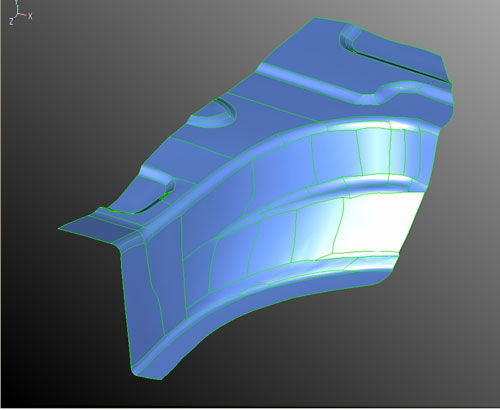
Polygons of scanned STL data —

—converted into a CAD model with valid surfaces and precise geometry, using CADdoctor EX3.0.
Call the CADdoctor
CADdoctor EX3.0 includes expanded capabilities for data translation end-to-end throughout product development—from scanned geometry for modeling to surface preparation for molding and manufacturing parts. It is said to promote process automation, reduce design and manufacturing times, and improve product data quality.
As computer-aided design (CAD), engineering (CAE), and manufacturing tools (CAM) have become more complex, the drive to seamlessly share data between them has grown stronger. There are, however, serious challenges to sharing because these tools have differing data input requirements. Some, like CAD, need extraordinary detail. Others, like CAE analysis tools, need very specific levels of simplicity. And CAM systems have exacting surfacing and manufacturability constraints.

Anark Core Workstation user interface was designed to be non-technical and easy to learn. Clockwise from left: the Product Structure Panel, the imported axle geometry in the 3D viewport, import and export actions (Deployment Settings Panel), CAD transformation action tabs (Transformation Inspector Panel).
CADdoctor assists in the translation of data into its most usable form for each application. For instance, a Reverse Engineering Option in the software can read the polygonal data in a stereolithography (STL) file and translate it into a CAD model with valid surfaces and boundaries, and precise geometry, as opposed to an approximation. The resulting data are usable without further repair or re-modeling in CAD, CAE, or even CAM applications for cutting, moldmaking, and other manufacturing processes.

This image collapses a CAD assembly into a single part, reorganizing the product structure for preparing CAD models for different suppliers or partners, or for creating vendor-specific BOM’s (bill of materials).
Other new options in CADdoctor EX 3.0 include:
• A Polygon Option that can check and repair holes, “noise,” and other defects that impede easy export of polygonal data from STL files.
• An Advanced Envelope Function that can “shrink-wrap” a 3D model to turn an assembly into a 3D solid, simplifying the surface accurately to share limited data with suppliers, provide the right level of detail for analysis software, or define surfaces for other tools.
• A Quality Check for Mold Manufacturing Option that checks models for draft angle, undercut, wall thickness, and other manufacturability issues. Early attention to manufacturing requirements in the design data can eliminate man-hours spent modifying molds.

Share only what needs to be shared. This axle assembly includes both cast and milled parts. You can remove product geometry that isn’t relevant for a particular vendor. Removing unnecessary or proprietary CAD components simplifies sharing data with multiple suppliers.)
More than a software translator
One example of how such technology is coming of age involves use of a software “translator” to meet complex interoperability needs. One example, the Anark Core, adds product restructuring capabilities, expanded PDM server integration, and support for SolidWorks, Inventor, ACIS, and CATIA V5 visualization data to its automated 3D CAD transformation platform. The new platform adds expanded conversion, transformation, and automation capabilities to cost-effectively prepare 3D product design data for visualization, simulation, CAE, and supply-chain-data-exchange applications.
The Core platform quickly and easily transforms native 3D CAD data for use throughout manufacturing design, engineering, and support departments. Unlike conventional CAD tools and translators, Core lets you automate the modification of 3D product structure and geometry, and export revised product data into high-precision B-rep and lightweight mesh formats. The system creates “recipes” that can be applied automatically to revised product design data, saving countless hours of labor each time product designs are changed.
Problem: The proliferation of CAD design applications has given designers an array of powerful and affordable options to choose from. One consequence is that groups needing to share and access CAD data must wrestle with a multitude of different file formats, maintain non-design related seats of CAD design software, and train users for non-design related tasks.
Solution: The Anark Core Platform includes not just CAD translation between most popular CAD formats, but also tools to provide use-case-specific, derivative CAD data tailored to the requirements of each recipient.
OEM-Supplier data exchange Visualization and Simulation applications CAE model preparation
Technical publications
Problem: A recent survey conducted by CADCAMNet shows engineers spent between 6-7 hours per week translating and preparing CAD data for suppliers or manufacturing partners. Alarmingly, engineers at supplier companies who receive the data are spending 6-10 hours each per week on the same problem. Conventional 3D CAD design applications are complex, have steep learning curves, have little or no automation of any of these processes, and are often
ill-suited for typical CAD transformation tasks.
Solution: Core is an easy-to-use, high-volume, CAD transformation platform. It enables users to easily restructure product data using unique parametric selection tools and drag-and-drop workflow. Irrelevant, unwanted, or confidential features, parts, and assemblies can be removed in minutes.
Capturing transformation actions into a repeatable, automatable recipe and broad support for B-rep and mesh formats can save engineering efforts hours each time a design changes.
• Remove sensitive design data or IP reliably
• Ensures consistency by reducing human error
• Reduce amount of time spent on non value-adding tasks
• Ensures synchronicity between original design data and derivative models
Anark Corp.
www.anark.com/core
Elysium Inc.
www.elysiuminc.com
Filed Under: Software • 3D CAD, ENGINEERING SOFTWARE


Tell Us What You Think!