The first part of this article introduced the inductive proximity sensor. This second and final part looks at some more specifics of this sensor.
Q: Are there different architectures and implementations?
A: Yes, there are three basic types:
1) the magnetic elements alone are in the sensor. This separates the electronics from the sensing coils and provides the smallest, most rugged sensor, Figure 1.
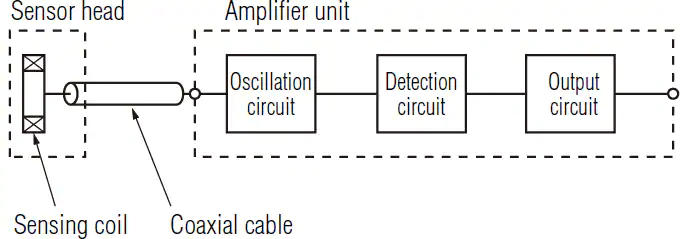
2) in the next group, the front-end oscillator and sensed-signal amplifier are in the sensor, and the amplified signal is then passed via a cable to the additional electronics for further conditioning and formatting.
3) It is now possible to incorporate the entire signal chain in the sensor assembly itself; some versions even digitize the conditioned analog signal, Figure 2.

The decision of which style to use depends on installation details, application specifics, cost versus performance, ease of use, and many other factors. There are also issues related to working with existing legacy installations. All three types are still in wide use.
Q: Is the sensing mode directional?
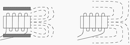
A: No, the basic sensor is omnidirectional which is desirable in some cases but not in others. For cases where directionality is needed, the solution is to magnetically shield the sensor, Figure 3.
Q: What are parameters to assess when selecting an inductive sensor?
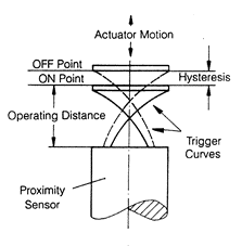
A: In addition to size, sensitivity needs to be matched to the application. It is usually specified as the maximum distance that will trigger a change in the output from the sensor to a square piece of 1-mm thick iron (type Fe 37), with side dimensions equal to the diameter of the sensing face. There are also related issues of hysteresis and repeatability, Figure 4, as well as temperature coefficients of response. Other considerations include operating frequency, power and current requirements, and interface type and format.
Q: How much does a sensor cost?
A: Prices for a basic sensor start at around $10 to $15, and range into the hundreds of dollars depending on size, accuracy, ruggedness rating, amount of embedded electronics, and other factors.
Q: Is the circuitry for using an inductive sensor complicated?
A: Yes and no. As with many sensor circuits, the basic design is straightforward. However, achieving accurate, consistent, and stable performance can be a challenge.
Q: How is this done?
A: Before ICs were available with their inherent capability of enabling use of circuit techniques which allow for sophisticated topologies to be easily implemented, it was done with discrete transistors and yes, even vacuum tubes. ICs offer not only ease of use, basic functionality, and enhanced performance, but other functions and features which benefit the user. Among the vendors of such ICs are Microchip Technologies, Renesas, and Texas Instruments.
The inductive sensor is an important component in the engineer’s menu of sensor options, as it is easy to use, rugged, effective, precise, and easy to install. Like its sibling the LVDT, it is available in many sizes, sensitivities, and electrical options, and is well worth considering in countless applications.
Related EE World Content
LVDT electronics, Part 1: Excitation and demodulation
LVDT electronics, Part 2: Interface circuitry
Inductance-to-digital converter is presented as industry’s first for position and motion sensing
Battery powered inductive proximity sensor sports 70-ft range
Inductive position sensor targets absolute position apps in industrial motors
Inductive proximity sensors with analog output from Automation Direct
Wireless inductive system 2 for wireless sensor connection
Magnet-free inductive position sensing targets automotive motor commutation
External References
Keyence Corp., “What is an Inductive Proximity Sensor?
Keyence Corp., “Categorization of inductive proximity sensors
Automation.com, “How Inductive Sensors Work
Fargo Controls, “Operating Principles for Inductive Proximity Sensors”
Microchip Technologies, “Robust, Low-Cost and Noise-Immune Motion-Sensing Inductive Sensors”
Renesas Electronics Corporation, “IPS2550 Inductive Position Sensor for High-Speed Motor Commutation (Automotive)”
Texas Instruments, “LDC1101 1.8-V High-Resolution, High-Speed Inductance-to-Digital Converter”
Filed Under: Sensor Tips