Design World

  • Home
  • Technologies
    • 3D CAD
    • Electronics • electrical
    • Fastening & Joining
    • Factory automation
    • Linear Motion
    • Motion Control
    • Test & Measurement
    • Sensors
    • Fluid power
  • Learn
    • Ebooks / Tech Tips
    • Engineering Week
    • Future of Design Engineering
    • MC² Motion Control Classrooms
    • Podcasts
    • Videos
    • Webinars
  • LEAP AWARDS
  • Leadership
    • 2022 Voting
    • 2021 Winners
  • Design Guide Library
  • Resources
    • 3D Cad Models
      • PARTsolutions
      • TraceParts
    • Digital Issues
      • Design World
      • EE World
    • Women in Engineering
  • Supplier Listings

When is the application of overvoltage safe (and common) for stepper motors?

By Danielle Collins | January 14, 2022

Share

For most types of motors, operating with a supply voltage that is higher than the rated voltage — referred to as overvoltage — can cause an increase in current, and heat, high enough to damage the coils and other motor components. But in some cases, a stepper motor can be operated at a voltage higher than rated voltage, without damaging the motor. Let’s look and when and why this is possible.


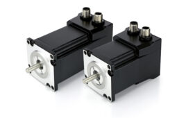
stepper motor
Image credit: Moons’ Industries

Stepper motor applications commonly use one of two types of stepper drive — a constant voltage drive (also referred to as an “L/R” drive) or a chopper drive.

As their name implies, constant voltage drives deliver a fixed, constant amount of voltage to the motor, equal to the motor’s rated voltage. With a constant voltage drive, the motor’s resistance (R) limits the amount of current that can build in the windings, and the motor’s inductance (L), determines how quickly the current builds, or rises. (The term “L/R drive” is in reference to the motor’s time constant, which is defined by the inductance, L, divided by the resistance, R.)

At low speeds, motors operated with constant voltage drives provide good torque and smooth rotation. But as motor speed increases, the current in the motor windings doesn’t have sufficient time to rise during each drive pulse, so torque production falls off.

While higher current (and torque) could be obtained by suppling the motor with higher voltage (overvoltage), this causes a problem with the motor’s temperature rise, as the “off” time of the motor — the amount of time when no voltage is applied — must be long enough to allow cooling and prevent heat damage.


Because constant voltage drives deliver limited torque at higher speeds, many stepper motor applications use chopper drives. Chopper drives are also referred to as “constant current” drives because they monitor and regulate the current to the motor, rather than the voltage. The term “chopper drive” comes from the fact that the drive rapidly switches the voltage on-and-off (referred to as “chopping” the voltage) to control the amount of current delivered to the motor.

chopper drive voltage and current
Relationship between voltage (green) and current (blue) when a stepper motor is driven with a chopper drive.
Image credit: Clippard

To ensure the stepper motor receives enough current to produce the rated torque, regardless of motor speed, a very high voltage, or overvoltage, is provided by the chopper drive. This high voltage ensures a fast current rise, so even if the motor is operating at high speeds, it receives a constant RMS (root mean square) value of current to produce the required torque.

stepper motor overvoltage
The higher the ratio of the supply voltage to the motor’s rated voltage, the more the torque speed curve is “pushed out.”
Image credit: Ametek

But why is it ok to drive a stepper motor with overvoltage when using a chopper drive? Because a chopper drive places a resistor in series with each motor winding to monitor the motor current.

When the voltage across the resistor reaches a predefined high level, which represent’s the motor’s rated current (I = V/R), the voltage supply is switched off. And when the voltage across the resistor drops below a preset level, the voltage supply is switched on again. Pulse-width modulation (PWM) is used to vary the width of the output pulses from the drive, according to how much voltage “on” time is needed.

The result is that torque can be controlled more precisely, and more torque can be produced at higher speeds, without the heating problems that would occur if overvoltage was applied with a simple L/R, or constant voltage, drive.


Filed Under: Motion Control Tips


Related Articles Read More >

Schneider Electric launches Universal Automation Discovery Packs to foster industrial innovation
Encoders from SIKO support Industrial Ethernet
Draw-wire encoders from SIKO measure position, speed and inclination
Incremental encoders configurable via NFC (near-field communication)

DESIGN GUIDE LIBRARY

“motion

Enews Sign Up

Motion Control Classroom

Design World Digital Edition

cover

Browse the most current issue of Design World and back issues in an easy to use high quality format. Clip, share and download with the leading design engineering magazine today.

EDABoard the Forum for Electronics

Top global problem solving EE forum covering Microcontrollers, DSP, Networking, Analog and Digital Design, RF, Power Electronics, PCB Routing and much more

EDABoard: Forum for electronics

Sponsored Content

  • Global supply needs drive increased manufacturing footprint development
  • How to Increase Rotational Capacity for a Retaining Ring
  • Cordis high resolution electronic proportional pressure controls
  • WAGO’s custom designed interface wiring system making industrial applications easier
  • 10 Reasons to Specify Valve Manifolds
  • Case study: How a 3D-printed tool saved thousands of hours and dollars

Design World Podcasts

May 17, 2022
Another view on additive and the aerospace industry
See More >
Engineering Exchange

The Engineering Exchange is a global educational networking community for engineers.

Connect, share, and learn today »

Design World
  • Advertising
  • About us
  • Contact
  • Manage your Design World Subscription
  • Subscribe
  • Design World Digital Network
  • Engineering White Papers
  • LEAP AWARDS

Copyright © 2022 WTWH Media LLC. All Rights Reserved. The material on this site may not be reproduced, distributed, transmitted, cached or otherwise used, except with the prior written permission of WTWH Media
Privacy Policy | Advertising | About Us

Search Design World

  • Home
  • Technologies
    • 3D CAD
    • Electronics • electrical
    • Fastening & Joining
    • Factory automation
    • Linear Motion
    • Motion Control
    • Test & Measurement
    • Sensors
    • Fluid power
  • Learn
    • Ebooks / Tech Tips
    • Engineering Week
    • Future of Design Engineering
    • MC² Motion Control Classrooms
    • Podcasts
    • Videos
    • Webinars
  • LEAP AWARDS
  • Leadership
    • 2022 Voting
    • 2021 Winners
  • Design Guide Library
  • Resources
    • 3D Cad Models
      • PARTsolutions
      • TraceParts
    • Digital Issues
      • Design World
      • EE World
    • Women in Engineering
  • Supplier Listings