Increasing product complexity as well as unrelenting pressures to improve program cost and quality demands a collaborative design environment, in which information is always up-to-date and can be accessed as a “single source of truth” across all stakeholders.
To address these challenges, companies are increasingly transitioning to 3D model based environments as a means for communicating downstream manufacturing requirements i.e. adding Product and manufacturing information (PMI) such as geometric dimensions and tolerances, annotations directly within the 3D model. In such an environment, 3D models serve as a master data, depicting design intent more effectively to downstream users in manufacturing, assembly and inspection processes.
Geometric dimensioning and tolerancing (GD&T) is a universal symbolic and tolerancing language to describe part features and tolerancing value to manufacturing and suppliers. It has been traditionally applied to 2D drawings.
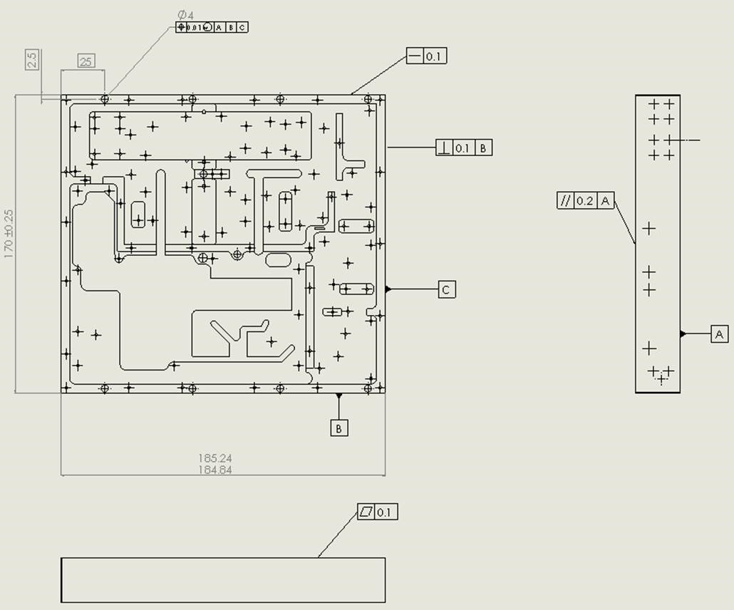
Figure 1: 2D Drawing with GD&T
With the advent of the Model-Based Enterprise, the classic 2D engineering drawings are being replaced with 3D models with all the product definition, geometric dimensions, tolerances (GD&T), datum features etc. being visually highlighted on a 3D model. By moving away from 2D drawings organizations expect to receive several benefits:
- Reduce the misinterpretation of designs by manufacturing and suppliers.
- Eliminate the time required to manually update drawings whenever design changes or engineering change orders (ECOs) are made.
- Accelerate manufacturing and inspection processes while simultaneously improves product quality.
With the added PMI information, performing a ‘design for manufacturing’ analysis upfront becomes more comprehensive. Not only can a design be checked as per its nominal dimensions but the specified tolerances can also be used to check for suitability of the selected manufacturing process. This helps determine the implications of the tolerances on manufacturing quality and cost.
The PMI information can also be used to confirm whether the part can be manufactured using a machine of a specified process capability. One of the secrets to making the Model-Based-Enterprise a reality in enabling upfront DFM using 3D PMI. Many forward thinking organizations have the DFM-MBE combination as a key element of their strategy. A Design-to-Cost approach is also highly benefited from a 3D PMI approach.
Despite many advantages, adoption of the complete 3D model based environment is still slow. Part of the reason is that adding 3D GD&T data to models directly is prone to errors in creation, as well as in consumption. You need to manually detail your 3D model and mistakes can be made while displaying the product and manufacturing information annotation accurately in 3D space.
With all the basic dimensions, symbols and notes being presented in 3D model, it also becomes overly complex and cluttered leading to misinterpretation of design intent. Refer to figure 2 which shows how cluttered a model can get when 3D annotations are added.
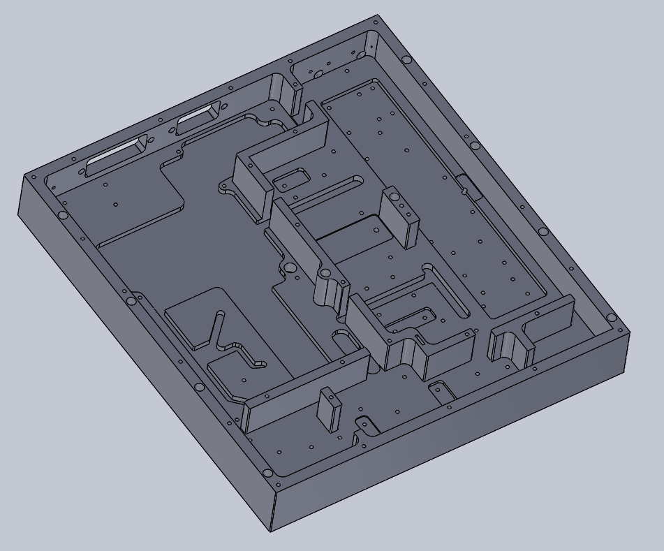
Figure 2: 3D Model without tolerances
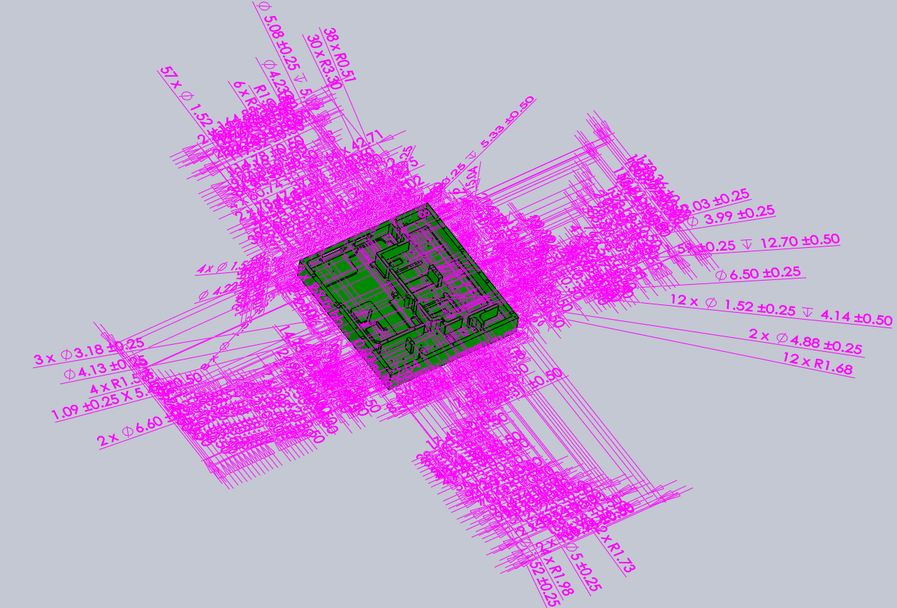
Figure 3: Model is toleranced but cluttered
The information needed across different functional groups such as manufacturing, inspection and assembly departments should be represented with absolute clarity and simplified viewing such that just by looking at the model they can understand the datum features and specification that they can use in various processes.
However, since MBE is still evolving, skills to create and interpret 3D GD&T are still few. Also CAD software functionality that support 3D GD&T from major vendors are also not very mature.
Any misinterpretation of design intent can lead to potential errors in manufacturing and huge losses.
What makes the interpretation accurate is dependent upon how the data is represented, i.e. the layout, symbols, formatting etc. are accurately added to depict form, function and orientation across functional groups.
The lack of a standardization pertaining to the use of PMI in 3D models is often considered to be a limitation. The designers should be aware of the 3D Digital Product Definition Practices standard ASME Y14.41-2012. This standard sets the guidelines to follow for tolerances, dimensional data, and other digital design annotations on 3D models.
Geometrics’ DFMPro encourages designers to consider downstream manufacturing and assembly best practices by simplifying the process. It takes into consideration the documented best practices in the form of rules and enables the design engineers to access this knowledge base, so that ‘right decisions’ based on the global and/or organizational standards can be taken upfront while designing the 3D model.
Thus DFMPro is also well positioned for effectively using PMI for manufacturability decisions. For example, as shown in Figure 4, the tolerance details related to countersink distance from the part edge can be from the PMI information in the model to check manufacturability of this model.
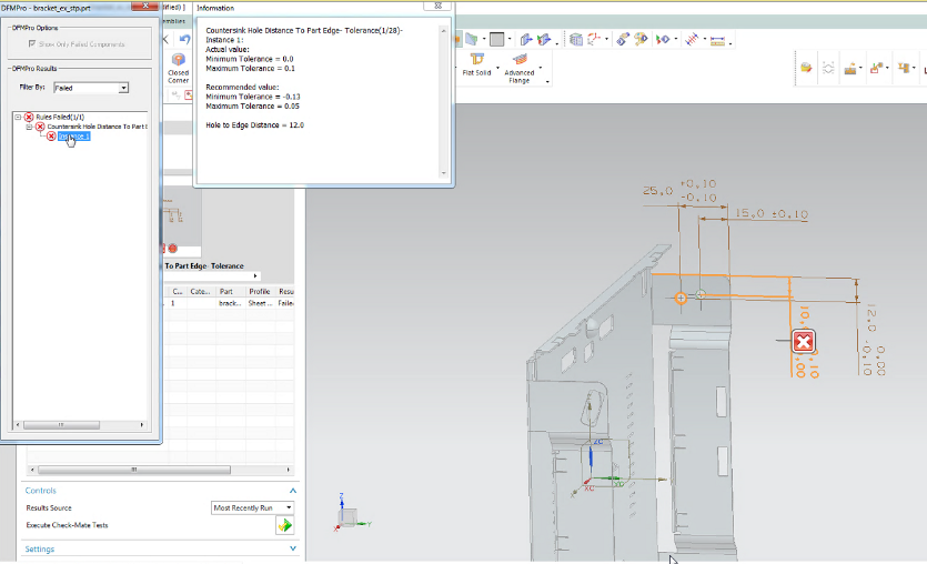
Figure 4: Design for Manufacturing Analysis using PMI information
A well annotated 3D model, results in less clutter and true understanding of design intent. Personnel in manufacturing and inspection can make more informed decisions to deliver a higher quality product at reduced cost and faster time to market. 3D Model based PMI helps build an environment characterized by effective communication and effortless manufacturing, thereby guaranteeing optimum productivity
Also minimal use of 2D drawings relieves the overtaxed engineers of the laborious process of creating and recreating it. This saves time and boosts the happiness quotient of the workforce – two essential elements of supreme productivity.
Filed Under: Rapid prototyping