Linear stage designs can range from long-stroke, high-load gantries to micropositioning and nanopositioning stages with light payloads. Although all linear stages are designed and constructed to provide high positioning accuracy and repeatability and to minimize angular and planar errors, stages for micropositioning and nanopositioning applications require additional considerations in component selection and design to achieve these very small, precise motions.
Micropositioning refers to applications where movements are as small as one micron, or micrometer. (One micron is on millionth of a meter, or 1.0 x 10⁻⁶ m.)
Nanopositioning refers to applications where movements are as small as one nanometer. (One nanometer is one billionth of a meter, or 1 x 10⁻⁹ m.)
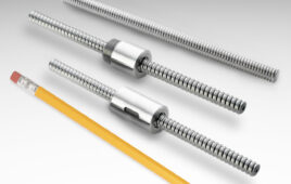
To achieve positioning in the micron or nanometer range, one of the key design principles is to eliminate as much friction as possible. This is why nanopositioning stages exclusively use non-contact drive and guiding technologies. For example, the driving force for a nanopositioner is typically provided by a linear motor, piezo actuator, or voice coil motor. On the other hand, micropositioning can often be achieved with more traditional mechanical drivetrains such as ball and lead screws, although linear motors are also sometimes used for micropositioning applications.

Image credit: PI
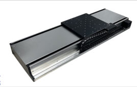
Friction-free guide technologies used for nanopositioning include air bearings, magnetic guides, and flexures. Because these technologies don’t involve rolling or sliding contact, they also avoid the backlash and compliance that degrade positioning accuracy in traditional mechanical transmissions. For micropositioning stages, non-recirculating linear guides are typically the best choice, since they don’t experience pulsations and varying friction levels from balls entering and exiting the load zone. However, some high-accuracy recirculating linear guides have been optimized to reduce these pulsations and friction variations, making them suitable for micropositioning applications — particularly those with longer total stroke lengths.

Image credit: Aerotech
In addition to friction and backlash, other effects, such as hysteresis and creep, can interfere with the system’s ability to position at the micron or nanometer level. To deal with these effects, micropositioning and nanopositioning stages are typically operated in a closed-loop system using a position feedback device that has a much higher resolution than the required positioning accuracy. This often means single-micron (or better) resolution for micropositioning applications and single-nanometer resolution for nanopositioning requirements.
Technologies that can provide these extremely high resolutions include glass scale optical encoders, capacitive sensors, and interferometer-based encoders. However, because nanopositioning stages are typically very small devices, capacitive encoders — which can be constructed in a very small footprint — are typically the best option. For micropositioning stages, high-resolution magnetic encoders are sometimes used as well — particularly when the environment involves fluctuating temperatures or high humidity.
Despite their special design and construction, micropositioning and nanopositioning stages are relatively easy to customize — especially in terms of materials, finishes, and special preparations — and apply in unique applications. Case in point: Stages that are constructed with friction-free components are typically suitable for cleanroom and vacuum applications, since they don’t create particulate matter due to rolling or sliding friction and don’t require lubrication. And if a non-magnetic version is required, standard steel components can be easily replaced with non-magnetic alternatives without concerns regarding reduced load capacity. In many applications where micropositioning and nanopositioning stages are used, the machine design includes features such as damping mechanisms that can counteract even the slightest vibrations and advanced control algorithms to compensate for disturbances.
Feature image credit: ASML

Filed Under: Linear Motion Tips