Although additive manufacturing is often called 3D printing, it’s not literally “3-Dimensional” in that it’s actually a series of two-dimensional layers stacked on top of one another to form a part. This layering process can create varying strength relative to the properties of each plane. In advanced applications where consistent strength throughout the part is required, the layering process creates anisotropy, or varying properties in different directions.
The layering process produces concentrated strength in the XY dimensions and weaknesses in the Z direction and as a result, engineers are forced to design around the lowest mechanical properties in Z. All additive manufacturing processes are susceptible to this deficiency that can inhibit design freedom. Dry-blended carbon fiber-filled materials for Laser Sintering (LS) in particular, although incredibly strong and dense, can exacerbate anisotropy.
In this article, we explore causes of anisotropy in LS carbon fiber-filled materials, present solutions, and highlight a new LS material with isotropic properties being developed by Stratasys Direct Manufacturing, EOS, ALM, and The Boeing Company.
SOURCES OF ANISOTROPY IN CARBON FIBER-REINFORCED POLYMERS
LS builds complex parts directly from 3D CAD data using powdered thermoplastics. A laser melts and forms each layer of the part, the build platform slightly descends, a recoating blade sweeps a fresh layer of powder over the last layer, and the process continues until the model is complete. The part is built in self-supporting powder which is brushed off during post-processing. It is an affordable way to build durable, complex production parts in low volumes and is often used for robust aerospace, transportation, and oil and gas applications.
LS uses semi-crystalline polymers which exhibit a combination of high mechanical properties, high softening temperatures, and high long-term stability. These semi-crystalline polymers are either pure unfilled nylons commonly used for concept modeling, non-functional prototypes, or small series productions. Nylons reinforced with functional micro fillers are commonly used for more advanced prototyping and production applications.
While LS is one of the most popular 3D printing processes for freeform fabrication, engineers still struggle with designing for the anisotropic process. Anisotropy in unfilled LS nylons can deviate anywhere from five to eight percent between XY and Z mechanical properties, while carbon fiber-filled nylons jump to much higher dimensional deviations of 30 to 70 percent between XY and Z properties. Although carbon fiber-reinforced LS nylons have high heat deflection, chemical resistance, and tensile strength, their properties vary between the X, Y, and Z axes. Engineers end up designing for the lowest mechanical properties in Z and have to take anisotropy within the XY plane into account.
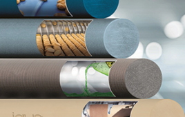
The discrepancies between the properties in the X, Y, and Z orientations in carbon fiber-reinforced polymers is due to a combination of the material’s properties and the LS recoating process. Standard polymer composites are produced through a dry blending process in which the plastic particles, fibers, and fillers are simply mixed together as shown in the microscopic image below (Fig. 1).
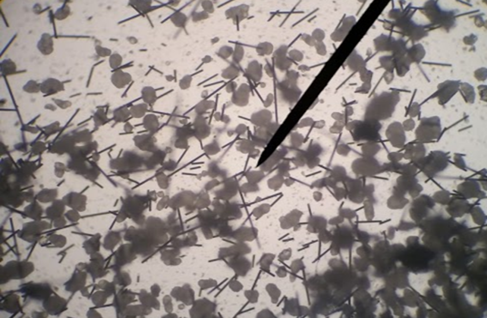
Figure 1: In this microphotograph of a dry blended LS carbon fiber composite, the plastic particles and fibers are clearly visible throughout the powder. Image courtesy of EOS.
Because the carbon fibers are long, thin, and separate from the plastic particles, they tend to align along the direction of the recoating blade as it pushes a new layer of powder over the top of the previous sintered layer. Since the fibers are predominantly oriented along one axis of the part, there is a greater percentage of anisotropy. The top half of Table 1 illustrates the differences between strength in the X, Y, and Z orientations for EOS CarbonMide carbon fiber-reinforced LS composite, with a greater concentration of fibers aligned on the X axis.
In order to minimize the inconsistencies to move toward isotropic reinforcement, the orientations of the fibers need to be more evenly distributed throughout the part.
IMPROVING FIBER DISTRIBUTION
LS material developers are discovering new methods for producing LS carbon fiber composites that randomly orient the fibers throughout X, Y, and Z to achieve better isotropy. One method is encapsulating the fiber within the plastic particles which has shown significant improvements in fiber orientation distribution (Fig. 2).
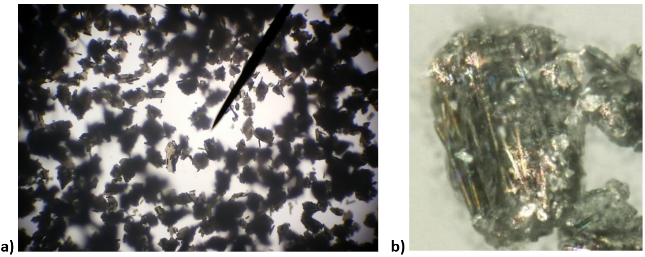
Figure 2: Encapsulated carbon fiber composite (a). A single powder particle with encapsulated carbon fiber (b). Images courtesy of EOS.
The carbon fibers are encapsulated in the plastic in varying orientations to prevent them from aligning with the recoating blade along the X axis. As the laser hits the powder, the particles are spread in every direction in the melt pool (Fig. 3a). A micrograph of a cross-section of a finished part reveals carbon fibers oriented randomly in and out of the plane (Fig. 3b).
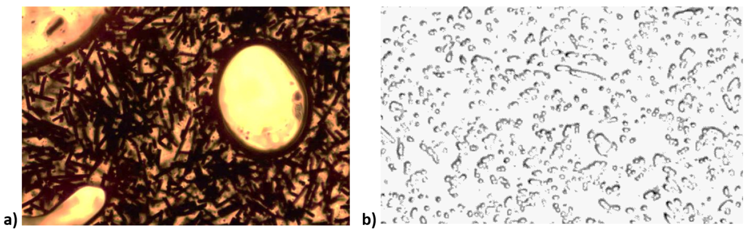
Figure 3: Encapsulated carbon fibers during (a) and after laser sintering (b). Images courtesy of EOS.
The result is more uniform reinforcement. The table below shows a comparison between EOS CarbonMide, a dry-blended carbon fiber-reinforced LS composite, and EOS HP11-30, an encapsulated carbon fiber-reinforced LS composite. While both materials use a Nylon 12 as their base polymer, the method of carbon fiber reinforcing creates a notable difference in mechanical properties.
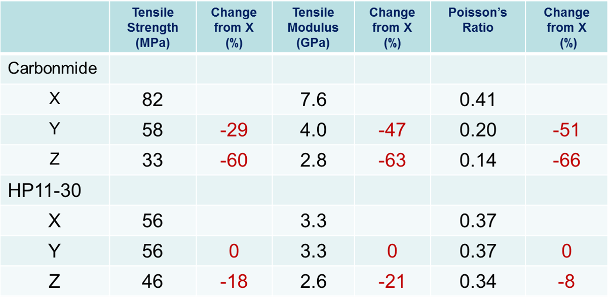
Table 1: Courtesy of Stratasys Direct Manufacturing.
DEVELOPING AN ISOTROPIC HIGHPERFORMANCE THERMOPLASTIC
While isotropy is universally beneficial for all applications, it’s in high demand for functional end-use applications in aerospace, transportation, and energy. The Boeing Company recognized a gap in isotropic LS materials for advanced applications and approached EOS, a manufacturer of LS systems; ALM, the materials development arm of EOS NA; and Stratasys Direct Manufacturing, one of Boeing’s additive manufacturing service providers. The companies formed a team to develop an isotropic reinforced high performance LS thermoplastic.
PEKK (polyetherketoneketone) is a semi-crystalline thermoplastic from the polyaryletherketone (PAEK) family with high heat deflection temperature, excellent chemical resistance, and strong mechanical properties. While most LS materials require a heavy molecular additive to achieve flame retardancy, PEKK is naturally flame retardant and lightweight.
ALM formulated PEKK for LS with encapsulated carbon fibers to run on a EOSINT P 800 machine. EOS provided hardware and software modifications to its standard EOSINT P 800 machine as well as optimized process parameters in order to process the carbon fiber reinforced PEKK and account for the unique material processing challenges. After EOS pinpointed the initial machine modifications, Stratasys Direct Manufacturing and The Boeing Company began testing the new material and process. The table below shows normalized data comparing carbon fiber encapsulated PEKK (HT-23), carbon fiber encapsulated Nylon 11 (HP11-30), and flame retardant Nylon 11 (FR-106). HT-23 exhibits isotropic properties combined with improved strength, stiffness, flame retardancy, and glass transition temperature.
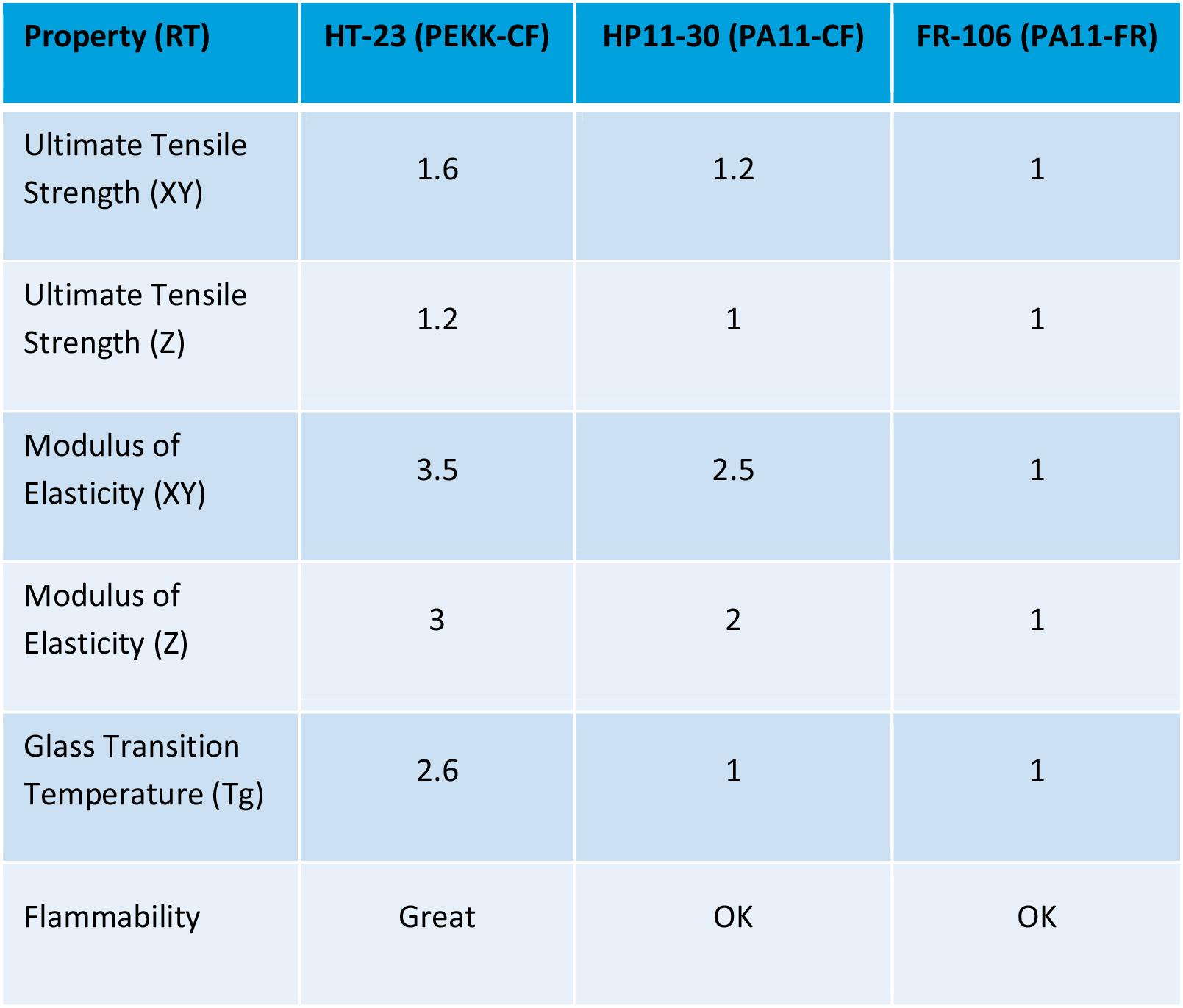
Table 2: Courtesy of Stratasys Direct Manufacturing.
The team is continuing to test and validate encapsulated carbon fiber PEKK for LS and has already used some parts for Boeing’s ecoDemonstrator program, which tests new technologies to reduce aviation’s environmental impact.
This article was written in partnership with Andreas Pfister, Senior Scientist, EOS; Sybille Fischer, Material & Process Developer, EOS; Rick Booth, Chemist, Advanced Laser Materials; Brett Lyons, Product Development, Materials Integration, Boeing; and Chris Robinson, 3DSIM.
This article originally appeared in the May/June 2016 print issue of Product Design & Development.
Filed Under: Materials • advanced