Some advanced motion-control applications — especially in the semiconductor and medical industries — need changes to target positions on the fly. Usually, the need for position changes arises from some position error detected by a vision-measurement system. Here, the goal is to get the machine to move quickly towards the final target; capture a picture; calculate needed corrections; and then get to the new position at maximum possible speed.
A machine’s overall throughput depends on fast, smooth motion and stable position corrections. That’s the case in some pick-and-place machines where vision-system measurements check the alignment of picked objects and determine all the adjustments the machine must make to move objects properly. Another application example is a wire-bonding application in which vision measurements quantify how much correction a machine axis needs to get to the proper location for a weld.
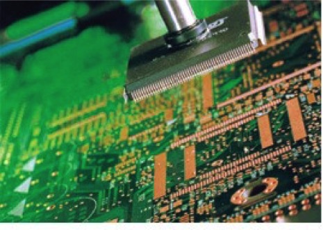
Now, one new system integrates vision and control functions to quicken the task by more than 30% in some cases. Called Elmo Flying Vision, the control function lets machines update position without reducing speed … but maintain maximum accuracy and stability. It’s suitable for PCB drilling, flying probes, cut-to-length tasks, and any machinery that needs to make quick position corrections. More after the jump.
Case in point: Wafer-handling application
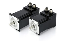
Consider an application in which a surface mount technology (SMT) machine drives two gantries simultaneously. SMT machines are pick-and-place designs in the semiconductor industry to put surface-mount devices on printed circuit boards. In our example, both gantries use an Elmo Gold servo drive on each axis:
- X1 and X2 work as a master-slave pair in MIMO-based gantry control architecture.
- Y works as a two-dimensional synchronized machine coordinate system (MCS) grouped with the X1-X2 gantry axes
- Z is the vertical axis
- Theta is the rotational axis (driven by a miniature servo drive)
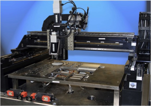
All ten drives in the system run off a single Elmo G-MAS multi-axis controller via EtherCAT. Vision components attach to each of the two gantries where the SMT’s pick-and-place trajectories regularly pass. The axes must run at the highest possible speed and precision, so the controls smoothly move them past the camera location from different pick-and-place positions at high speed … without stopping during image captures.
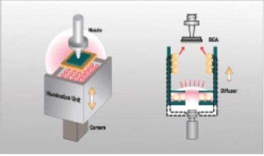
When the SMT part arrives just above the camera location, it triggers a tabulated position-based output compare — a 2×OC camera function. The first OC powers up an LED flash just before the image capture. The second OC prompts the camera to capture an SMT rotational-angle image. Next, an upper-level host computer or the camera itself processes the image information to get rotational and X-Y offset coordinates to relevant system axes just before final part placement.
The host computer can send final coordinates to the G-MAS during motion via EtherNET, as it has relatively abundant time (from the moment of image capture until a few miliseconds before the SMT sets the part down) to process the data and send final offset coordinates to the axes’ drives.
Distributed control speeds response
For these applications, Elmo’s distributed gantry control eliminates excessive fieldbus loads with a propriety serial-communication channel between the gantry servo drives. It defines one axis as gantry master, which in turn tracks the slave, computes all MIMO control laws, and keeps axes synchronized to the drive PWM level. This structure relieves the G-MAS controller from gantry-MIMO control algorithm operation … and lets the controller regard the X1-X2 gantry drives as a single X-axis drive on the network level. The controller even groups this “single axis” with the Y-axis to get quick (and synchronized) X-Y machine motion.
Elmo suggests two possible machine setups. As mentioned, our vision-assisted gantry’s strength is highly synchronized X-Y motion and the option to zip the end effector past a camera station with smooth position, velocity, and acceleration and deceleration profiles.
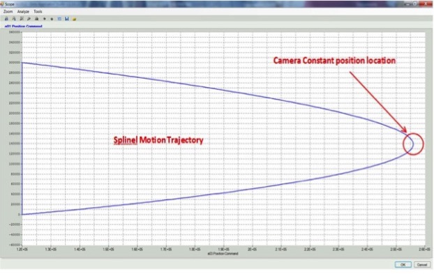
One option is to use two-dimensional spline motion. Elmo software lets users build spline trajectories in several different ways. One method (most suitable for the vision-assisted gantry we cover here) lets the user set a predefined table of spline positions limited by a velocity vector, acceleration-deceleration rates, and jerk. Two-dimension X-Y tabulated splines then make the gantry end effector pass through all spline-defined positions at the highest possible speed and precision.
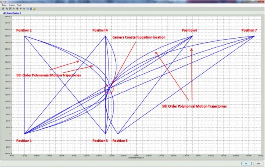
Another option is to use a special polynomial function-block mechanism. This G-MAS functionality lets engineers build synchronized motion trajectories using special segmented motion function blocks. In this mode, the user defines auxiliary and final position points as part of the whole motion trajectory. The G-MAS profiler passes through the auxiliary position using a polynomial transition trajectory. This function makes it easier for engineers to build complex motion trajectories that define position and velocity with smooth acceleration (and deceleration) and limited jerk.
A “speed override” function on the G-MAS can accelerate and decelerate the machine along the motion trajectory as a function of waiting time, until it gets final X-Y and rotational coordinates from the camera. This optimizes timing for each pick-and-place cycle to boost throughput.
Another G-MAS feature is how it can superimpose motions. The controller links a virtual axis to any standalone or grouped axis. The superimposed positions of the real and virtual axis trajectories become the final position of the real axis trajectory. So, engineers can add an offset position to any axis on the fly — even while the machine moves through original motion trajectories predefined by motion function blocks — without forcing any slowdown.
Two tabulated OC functions trigger the camera flash and image capture as functions of machine position along the motion trajectory. This synchronizes camera operation with G-MAS-prompted motion.
![]()
Filed Under: Motion Control Tips